Chemical & Biomolecular Engineering
Amine-Solvent Post-Combustion Carbon Capture
Team Members
- Camryn Capek
- Brianna Ryan
Overview
This project focuses on the capture of high-purity carbon dioxide (CO2) from the flue gas produced by a750 MW 1–on–1 advanced-class combined–cycle gas turbine (CCGT) power plant using CESAR1, a second generation, non–proprietary aqueous amine solvent. On a mass basis, CESAR1 consists of 27% 2-amino-2-methyl-1-propanol (AMP), 14% piperazine (PZ), and 59% water. The captured CO2 is intended for long-term geologic sequestration to reduce greenhouse gas emissions associated with large-scale power generation, particularly those driven from energy-intensive AI data centers.
The proposed design will be one of the largest carbon capture systems in the world, targeting 95% capture of incoming CO2. At this capacity, the plant is estimated to prevent approximately 2.35 million metric tons of CO2 annually from entering the atmosphere. This large–scale implementation is driven by increasing demand for low–carbon energy, evolving carbon taxation policies, and tightening environmental regulations.
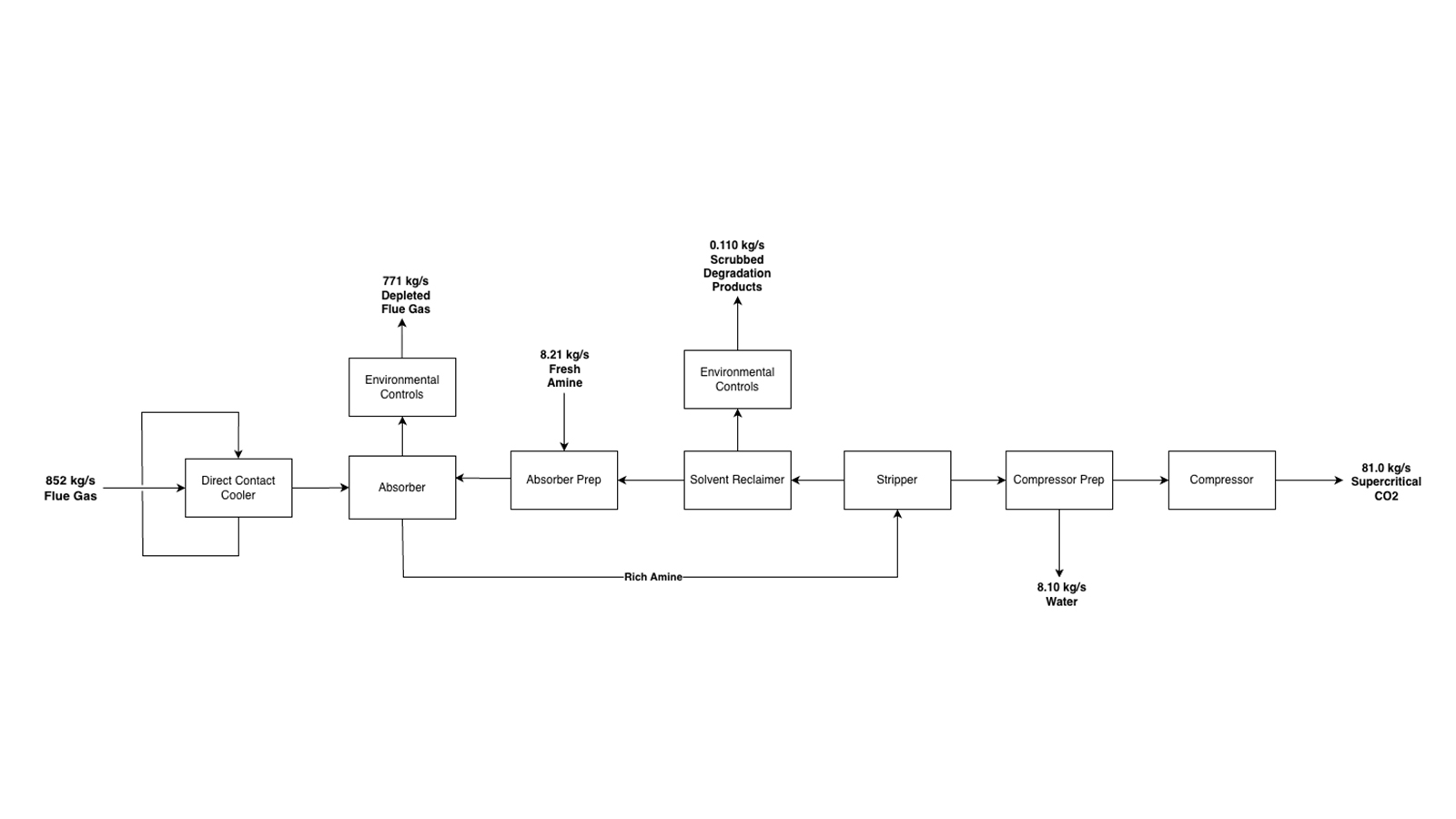
Flue gas from the CCGT is first cooled through a direct–contact–cooler (DCC) where the gas is cooled from 77°C to 30 °C using municipal water. This temperature reduction is critical, as CO2 solubility in the solvent increases at lower temperatures, therefore enhancing the downstream absorption performance. The cooled flue gas then enters the absorber column, where it flows counter currently to a CO2–lean CESAR1 solvent. The solvent is introduced above two packed sections to maximize mass transfer.
Within the absorber, CO2 is chemically absorbed (chemisorption) through exothermic reactions with the CESAR1 solvent. Due to the significant heat release, an interstage pumparound system is used to remove heat and maintain an optimal temperature profile within the column. The absorber consists of two packed sections followed by an upper water wash section. The water wash section cools the treated flue gas prior to release and removes any entrained solvent. This section includes two pumparound loops to regulate temperature and minimize evaporative solvent losses. Additionally, an activated carbon filter and continuous emissions monitoring systems ensure that the treated flue gas complies with environmental regulations.
The CO2-rich amine exiting the bottom of the absorber is pumped and preheated via heat exchange with the regenerated lean amine stream before entering the stripping column. In the stripper, thermal energy supplied by the reboiler drives the desorption reaction, releasing the CO2, and regenerating the lean solvent. The overhead vapor, consisting primarily of CO2 and water, is cooled to condense the water, producing a concentrated CO2 stream.
The regenerated lean amine stream is partially cooled and sent to a solvent reclaimer, where degradation products are removed. Fresh CESAR1 solvent is added to compensate for degradation losses. The reclaimed and replenished solvent is further cooled before being recycled back to the absorber column, completing the solvent circulation loop.
The purified CO2 stream is compressed through a multistage compression system to supercritical conditions, with interstage cooling to control temperature. The final CO2 product meets the purity requirement of 98 dry mole % CO2, which is required for pipeline transport.
The primary design challenge associated with this process is the large scale of the system, which requires careful consideration of equipment sizing, heat management, and mass transfer efficiency to maintain high capture rates.
Amine-Solvent Post-Combustion Carbon Capture (PCC) Facility Design

Team Members
- Trish Nguyen
- Bruce Baker
- Linh Pham
- Andrea Phan
Overview
Driven by the surging energy demands of computation-heavy datacenters, the utilization of natural gas-fired power generation is rapidly expanding. To align with strict emissions regulations and capitalize on 45Q sequestration tax credits, this project details the design of an advanced amine solvent Post-Combustion Carbon Capture (PCC) facility. Integrated with a 994 MW Combined Cycle Gas Turbine (CCGT) plant, the facility is designed to capture and process flue gas to produce pipeline ready, supercritical CO2 at >95% purity for transport to nearby sequestration hubs for storage in rock formations.
Sized to accommodate peak winter exhaust flowrates, the continuous facility processes flue gas using CESAR-1, a second generation non-proprietary amine solvent made of 2-amino-2-methyl-1-propanol (AMP) and piperazine (PZ), alongside utilities like cooling water, steam, hydrogen, and triethylene glycol (TEG). The process begins with about 6,700 kpph of hot flue gas containing 10wt% CO2 being cooled and pressurized in a direct contact cooler (DCC) before entering a packed absorber, where it makes countercurrent contact with the CESAR-1 solvent to extract CO2. To regenerate the solvent, the CO2 rich stream is heated in a stripping column using an energy-intensive reboiler. From there, the overhead CO2 undergoes three stage compression, followed by catalytic deoxygenation, reacting residual oxygen with hydrogen over a Pd/Al2O3 catalyst, and TEG dehydration. Finally, a two stage supercritical compression train pressurizes the dry, deoxygenated CO2 to approximately 120 bar to meet strict product quality specifications of less than 50 ppmv water and less than 1 ppmv oxygen.
Designing a financially viable and safe facility of this scale introduces several complex engineering challenges, particularly solvent degradation and high purity product requirements. AMP- and PZ- derived degradation compounds can impact operational cost, contaminate CO2 product, and cause corrosion within piping and equipment. This occurs under a variety of conditions such as high temperatures and presence of oxidizing species in the flue gas. To mitigate solvent degradation, two major pieces of equipment were implemented. An activated carbon mesh filters out the heat stable salts and degradation products that would have continued to circulate in the solvent regeneration loop. Additionally, the reclaimer removes and separates the remaining degradation products that the filter may have missed and prevents the recirculation loop from accumulating with those undesired byproducts. In implementing these two pieces of equipment, degradation product accumulation is reduced, and corrosion risks are minimized.
Another challenge in this design project was meeting the required purification specifications in multiple areas of the plant. First, emissions regulations do not allow the release of more than 200 tonnes per year of total volatile organic compounds (VOCs). AMP and other VOCs get entrained in the flue gas during the absorption step and release of these materials pose environmental hazards. Therefore, two water wash columns were implemented to wash out the entrained VOCs and return them to the solvent recirculation process to meet these regulations. As mentioned, product specifications of CO2 into shared pipelines require less than 50 ppmv water and less than 1 ppmv oxygen due to risks of corrosion. As a result, multiple purification steps are required to separate oxygen and water from the CO2 product to meet these standards.
Finally, because this process is inherently energy intensive, utility minimization was a critical design hurdle. To improve economic viability of the plant, extensive heat integration was required throughout the facility. By strategically recirculating hot process streams as preheaters, the design significantly reduces the overall external heating duties required by the plant, ensuring more efficient operation.
Crystallization of Uranyl Nitrate from Dissolved Spent Nuclear Fuel
Team Members
- Sarah Gas
- Austin Woodard
- Carsen Nelson
- Samuel Vrana
Overview
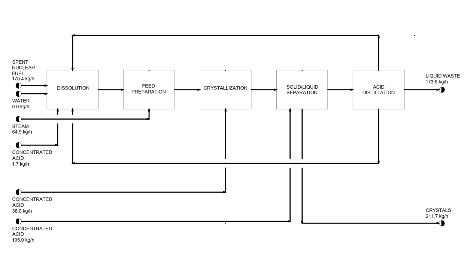
The United States currently stores over 95,000 metric tons of spent nuclear fuel (SNF) across 79 nuclear power plants in water-filled pools or dry casks. This project represents a strategic opportunity to recover over 91% of the remaining uranium, reduce dependence on foreignuranium, and convert a growing waste burden into usable fuel for advanced nuclear reactors.
This project focuses on the crystallization of uranyl nitrate hexahydrate (UNH) from SNF dissolved in nitric acid as an alternative to traditional organic solvent-based reprocessing. UNH is a key intermediate used primarily in nuclear fuel reprocessing to produce uranium oxides and can even be supplied to advanced reactors currently in development. Scientific demand also exists, both for nuclear research and for specialized uses such as electron-dense stain applications and structural stabilization in transmission electron microscopy.
The proposed reprocessing plant is designed to process 500 metric tons of uranium per year, equivalent to about 530 metric tons of SNF per year. Southeastern New Mexico has been selected as the reference site due to its proximity to nuclear fuel cycle infrastructure and proposed long-term waste storage facilities.
Downstream Process Decisions in Biologics Manufacturing: Affinity Column Placement, Resin Lifetime, and Real-World Tradeoffs
Team Members
- Ella DeMaster
- Joy Johnson
- Olivia Minderman
- Justin Sands
Overview
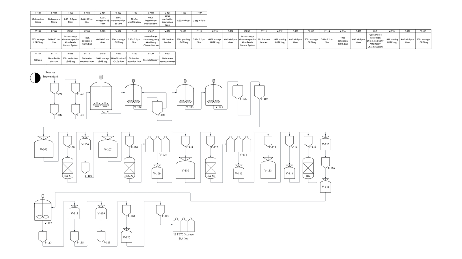
The product is a recombinant therapeutic enzyme produced in mammalian cell culture for the treatment of a life-threatening disorder. The protein requires several post-translational modifications to achieve full biological activity, and the downstream purification process must retain only the fully modified form while removing host cell proteins, product-related impurities, and other process contaminants.
The process is based on a 3,000 L bioreactor scale. Downstream purification was developed before bioaffinity chromatography was available and includes depth filtration, bioburden reduction, ultrafiltration/diafiltration, solvent-detergent viral inactivation, a four-column chromatographic sequence (three ion exchange steps and one hydrophobic interaction chromatography step), virus filtration, and a final UF/DF formulation step. Key raw materials include ion exchange and hydrophobic interaction chromatography resins, UF/DF membranes, virus removal filters, and buffer reagents. The final product must meet specifications for post-translational modification completeness, zymogen vs. active enzyme content, host cell protein levels, and biological activity.
The current process can meet quality specifications but suffers from limited robustness, with a batch failure rate driven by excessive host cell proteins in the product. Failed batches result in substantial economic losses due to wasted manufacturing costs, lost product revenue, and out of specification (OOS) investigation expenses.
To address this, the project evaluates retrofitting the existing purification train by integrating a bioaffinity chromatography resin at three candidate locations within the process: upstream of the existing chromatographic sequence to enable early impurity clearance, as a direct replacement for one of the existing chromatography steps, or as an additional polishing step at the end of the sequence. Each configuration is assessed for its impact on product yield, feasibility of process revalidation, and overall economics. Key design challenges include the high cost of the specialty bioaffinity resin, evaluation of product comparability of each option with the original process, anticipation of FDA regulatory requirements to confirm process and product comparability, and justification of capital investment through elimination of batch failures. The economic analysis includes detailed resin and buffer costing, implementation of the bioaffinity resin ligand leaching immunoassay, batch manufacturing times and scheduling, batch failure modeling, implementation timeline and process revalidation costs, and a probabilistic evaluation using Monte Carlo simulation to account for uncertainty in resin lifetime, cost variability, and process yield.
Production of Cumene from the Alkylation of Benzene and Propylene

Team Members
- Ashley Cook
- Thomas Haar
- David Karpf
Overview
Cumene, also known as isopropylbenzene, is a colorless organic liquid that is insoluble in water and soluble in most organic solvents. The target customers are large chemical manufacturers of phenol and acetone, and the goal of this project is to design a process to produce cumene from benzene and propylene. For this design, the target production rate is set at 300,000 metric tons of cumene per year. This capacity reflects a realistic scale for commercial operation and provides a solid basis for equipment sizing and economic evaluation.
Cumene has historically been classified as a high-production-volume chemical in the United States, with domestic output expected to continually increase in the coming decade. It is primarily produced as an intermediate for the manufacture of phenol and acetone, which are widely used in plastics, resins, and other industrial chemicals. Due to the high demand for these downstream products, efficient and economic production of cumene is an important industrial process. Beyond these major applications, cumene is also incorporated into various formulated products, including paint thinners, lacquers, and related solvent systems.
One of the main challenges in this process is the presence of multiple reactions. While the desired reaction produces cumene, a secondary reaction form DIPB. This reduces selectivity and increases the need for additional separation and recycle systems, adding complexity and cost.
Separation is another key challenge due to the similar volatilities of benzene and cumene. This makes distillation energy-intensive and requires multiple columns to achieve the desired product purity. The presence of DIPB further complicates the separation process.
The use of recycle streams, particularly benzene recycle, improves raw material efficiency but introduces process control challenges. Recycle loops increase the risk of impurity buildup and require careful monitoring to maintain stable operation.
Additionally, the process operates at elevated pressures to maintain propylene/propane feed in the liquid phase and achieve sufficient reaction rates. These conditions increase equipment costs and introduce safety considerations, requiring pressure-rated systems.
Production of Nitrile Butadiene Rubber
Team Members
- Kyle Nguyen
- Sam Peterson
- Sam Vadnais
- Nick Wayman
Overview
This project focuses on the design of a 50,000 tonnes per year nitrile butadiene rubber (NBR) production facility utilizing a continuous cold emulsion polymerization process. NBR is a widely used synthetic elastomerfor its chemical resistance to oils, fuels, and chemicals, and physical properties such as durability and flexibility. A target composition of 33 wt% acrylonitrile is selected to provide a balance between elasticity and chemical resistance, making the product suitable for applications such as seals, gaskets, hoses, and protective equipment. The motivation for this process stems from steady global demand growth and the constant need for reliablepolymers across multiple industrial sectors.
The process operates using free-radical emulsion polymerization of acrylonitrile and 1,3-butadiene in demineralized water at low temperatures (approximately 5–10 °C).
Propionic Acid Production

Team Members
- Alison Konz
- Emma Goeden
- Gabrielle Van Veldhuizen
- Jack Colwell
Overview
Propionic acid is a carboxylic acid used in industries including agriculture, food production, and pharmaceuticals. The focus of this project is production of propionic acid by the oxidation of propionaldehyde. The plant will produce 40,000 metric tons of propionic acid per year. The process outlined in this project is part of a larger process that produces propionaldehyde from ethylene before entering the system boundary. This is more cost-effective than buying bulk propionaldehyde and typically seen in industrial production. The propionic acid product is highly pure for use in food, agriculture, and pharmaceuticals. Propionic acid is used as a preservative for food, grain, and animal feed because of its bactericidal, fungicidal, insecticidal, and antiviral effects, elongating product shelf life. Additionally, it is used as a chemical intermediate in the production of pharmaceuticals.
Solution Mining of Soda Ash and Comparison of Processing Methods
Team Members
- Carson Nichols
- Micah Moore
- Travis Cloyd
- Kyle Givens
Overview
Global demand for soda ash (Na2CO3) continues to grow due to its widespread use and application. Soda ash is commonly produced from trona (Na2CO3·NaHCO3·2H2O) using solution mining in Green River, Wyoming where a fluid is injected into wells in the ground to dissolve the mineral. The resulting brine is then pumped to the surface. The conventional process relies on energy-intensive evaporation and thermal decomposition, resulting in high steam consumption. This project evaluates both the conventional process and a proposed carbonation– calcination route. The proposed process aims to reduce evaporation duty by precipitating sodium bicarbonate prior to calcination through carbonators. Carbonation requires additional gas handling and corrosion-resistant materials while shifting cost away from evaporators. The objective is to evaluate the economics of both processes and determine whether the proposed route justifies further investigation of a facility producing 1,000,000 tons per year of soda ash.
Vinyl Chloride: A Green Alternative
Team Members
- Aiden Gnuse
Overview
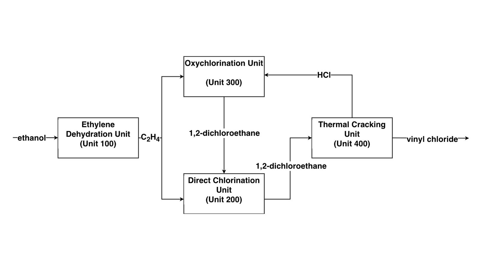
Vinyl chloride monomer (VCM), also known as chloroethene, is a colorless, flammable gas that serves as the essential building block for polyvinyl chloride (PVC). Over 95% of globally produced VCM is polymerized into PVC, one of the most widely used plastics in the world. PVC's versatility comes from its durability, chemical resistance, low cost, and ability to be formulated as rigid or flexible material through additives. Key uses of PVC (derived from VCM) include construction materials, medical devices, automotive parts, packaging, and consumer goods.
The purpose of this project is to evaluate the viability of VCM derived from Nebraska corn ethanol. VCM is conventionally produced through ethylene derived from petroleum. However, using a proprietary process developed by Lummus Technology, the required ethylene can be derived from corn ethanol produced here in the state. In the process, ethanol is dehydrated to ethylene over an alumina catalyst at 400-450°C and 8.5 bara. Conversion of the ethanol is complete and the selectivity to ethylene is over 99%. Such a process renders the produced VCM and the PVC product “green”, as the process no longer derives its feedstock from petrochemicals.