Electrical & Computer Engineering
Bionic Arm
Team Members
- Dominic Morris
- Jesse Sandoz
- Saleh Alnajem
- Jacob Burger
Overview
This project is an EMG bionic arm designed to assist people who have trouble moving their elbow. The arm detects electrical signals from the user’s muscles and helps move the elbow joint, providing support for daily activities and rehabilitation.
A motor with a planetary gear system powers smooth, precise motion at the elbow. Sensors and limit switches prevent the arm from moving beyond safe limits. A kill switch, start switch, and reset switch give the user full control.
An RP2040-based microcontroller processes the muscle signals and sends commands to the motor through H-bridges. The entire arm runs on a single adjustable power source for consistent performance.
The arm is lightweight and compact, attaching securely to the user with straps. For demonstrations, it can also operate from a stand.
This EMG bionic arm combines engineering and biomedical technology to support natural movement. It shows how assistive devices can enhance mobility for people with limited arm function and has potential applications in rehabilitation and daily life assistance.
Claw CubeAI
Team Members
- Nye Cha
- Mason King
- Sebastian MacNabb
- Cirilo Mejia
Overview
The product being designed is a moving claw device that will be able to locate a specified object within its field of view and relocate the object to a specified location. This will be done by having the claw move to be above the object, grab it, and then move it to a desired location. This will be done using image-based A.I. that will be able to recognize a stop sign on top of any relevant objects. There will also be a level of optional human-based input for testing.
The software will capture an image of the area, and it will check to see if the object is present. If it is then it will prompt the user to choose where the object should be moved to. This will begin the movement of the base and claw. During the first phase of moving the claw to the object, if that object is interfered with or moved outside of the field of view, then the operation will cancel and the claw will move back to its initial position. If the object is untouched then the claw will arrange itself over the object and stop. Then the base that holds the object will raise itself to the claw and then the claw will grab the object. Then the base will lower itself and the claw will begin moving the object to the desired position. Once that is done the base will raise again and the claw will release the object. Finally the base will lower one more time and the claw will return to its resting position.
Manual mode is operated with the touch screen. The possible option for manual mode is moving the claw, grabbing and releasing the claw, and lowering and raising the base.
FlexMaze
Team Members
- Keithen Cudly
- Hunter Tridle
- Jared Ponce
- Daniel Sotelo
Overview
Our device transforms muscle movements into controls for a game. EMG sensors are attached to the left and right biceps to detect electrical signals produced during muscle flexion. These signals are compared to determine the user’s intended direction of movement. The resulting command is then transmitted wirelessly to a computer running the game.
The game is a Pac-Man–style maze, where the user can move up, down, left, and right using only muscle flexion.
The system is designed to be accessible to a wide range of users, which is why it includes adjustable settings. The sensitivity of the EMG sensors and the speed of the in-game player can both be modified, allowing users to find the setup that best fits their preferences, whether that means requiring stronger muscle activation or increasing the game’s difficulty.
Beyond gaming, this device demonstrates how muscle-based controls can be applied to assist individuals with limited mobility. For example, similar technology could be used to control a wheelchair through muscle flexion. With further development, this approach has the potential to improve independence and quality of life for many users.
Ground Soil Moisture Monitor
Team Members
- Treydan Anderson
- William Fiddelke
- Sam Suppes
- Leighton Jeppson
Overview
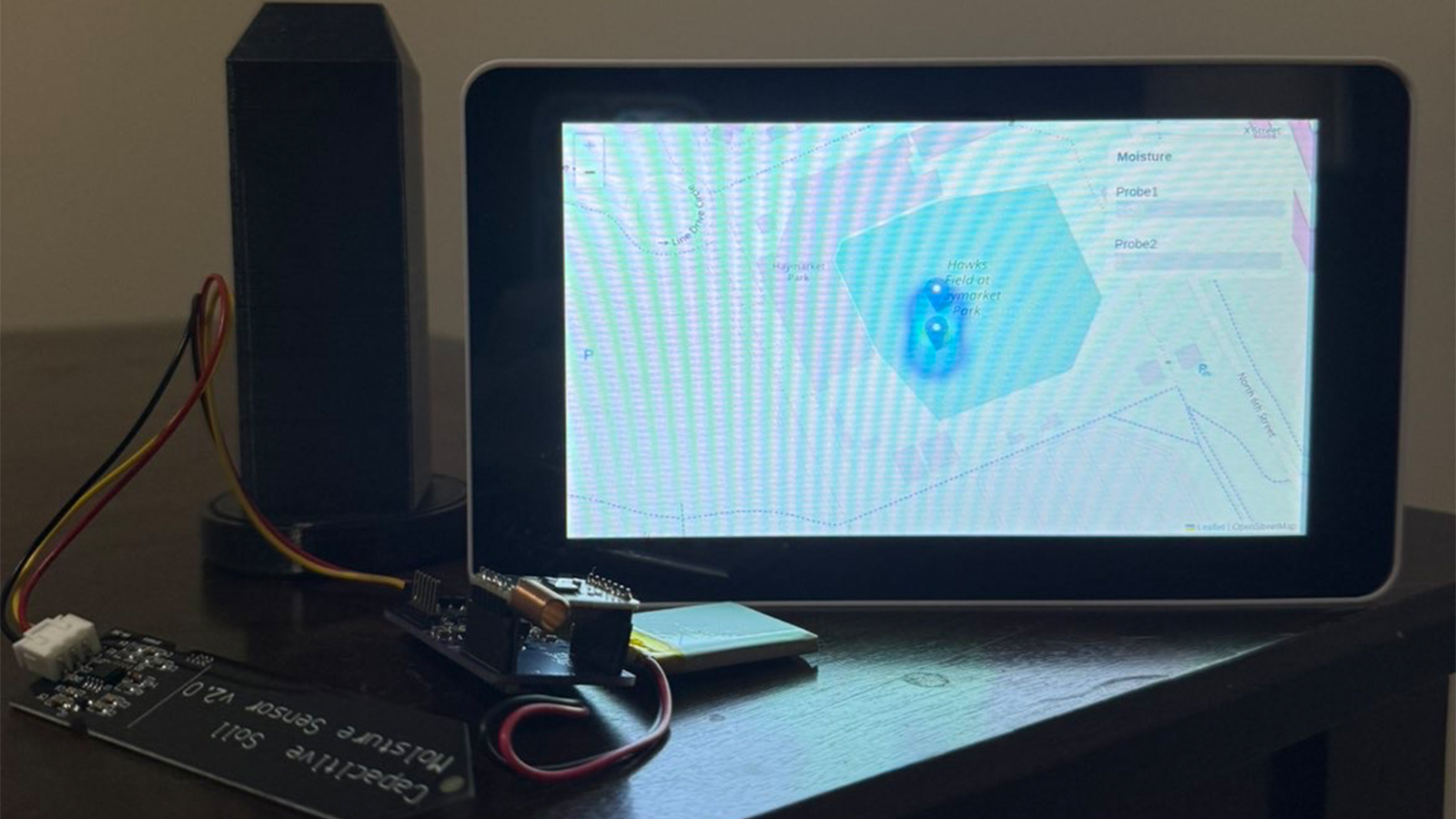
This project is a long-term underground soil moisture monitoring system designed to continuously collect, process, and visualize environmental data. Its primary function is to measure soil moisture at multiple locations and translate those measurements into meaningful, real-time visual outputs. By combining durable sensing hardware with wireless communication and data visualization tools, the system enables users to monitor moisture distribution over time and across space, supporting applications such as precision agriculture, irrigation optimization, and environmental analysis.
At the sensing level, capacitive soil moisture sensors are embedded underground to measure volumetric water content. These sensors are selected for their durability and resistance to corrosion, making them suitable for extended deployment in soil. Each sensor is connected to a custom designed MSP430 based printed circuit board (PCB), which is housed inside a protective 3D printed enclosure. The enclosure shields the electronics from moisture, pressure, and environmental degradation while allowing accurate sensing.
The MSP430 microcontroller on the PCB serves as the central processing unit for each node. It samples the analog output of the moisture sensor using its onboard ADC, converts the readings into calibrated moisture percentages, and formats the data for transmission. The system is designed with low-power operation in mind, allowing periodic sampling and efficient long-term use in the field.
Data from each sensing node is transmitted wirelessly using a LoRa communication module integrated with the PCB. The MSP430 interfaces with the LoRa transceiver via SPI, sending structured data packets that include the node identifier, moisture percentage, and raw ADC values. These packets are received by a central receiver connected to a Raspberry Pi, which acts as the primary data aggregation and visualization hub.
The Raspberry Pi processes incoming data and displays it locally on an attached LCD screen, providing immediate feedback on system performance and sensor readings. In parallel, the data is logged and exported in a structured format including timestamps and associated spatial coordinates for each node. This dataset is then used by GIS software ArcGIS to generate spatial visualizations.
Within the GIS environment, the collected data is rendered as a heatmap, illustrating variations in soil moisture across the monitored area. This visual representation allows users to quickly identify patterns, detect dry or saturated zones, and make data driven decisions. By integrating sensing, embedded processing, wireless communication, and spatial analysis, the system provides a complete and scalable solution for long-term soil moisture monitoring.
Husker Power
Team Members
- Aiden Lammers
- Andrew Stalder
- Grant Lewandowski
- Camrin Coco
- Grady Sheets
Overview
The Husker Power project is a portable USB-C power supply aimed to make an affordable, accessible, and user-friendly alternative to traditional lab power supplies. Traditional lab power supplies are often bulky, expensive, and non-portable, making them quite the hassle to access. The Husker Power product allows users to generate adjustable voltage and current outputs from a USB-C source.
The power supply has the capabilities of outputting a voltage range of 0.8V to 20V, with varying max output power. This allows users to use this power supply for a wide range of applications, such as low power electronics testing to moderate load prototyping. Safety features have also been implemented to prevent the supply from exceeding the user set current limit. These safety features include short-circuit protection, over-voltage protection, and thermal shutdown.
The hardware of the design is centered around an integrated buck-boosted converter, allowing efficient voltage regulation. This converter is paired with a precision current and power monitoring chip to get real time measurements of output voltage, current, and power. These components are connected to a microcontroller that allows the whole product to communicate. The entire system is set upon two different custom made circuit boards, the microcontroller board and the power electronics board.
One of the main focuses of the project is the simplicity of the user interface. The product has three different push buttons and an on/off switch to make it easy for users to navigate LCD displayed values and adjust voltage and current limit values easily. The product also has an incorporated LCD screen to provide clear and real time system parameters. Additionally, the system includes a serial interface allowing users to control the power supply from a computer. This feature allows a smooth user experience.
The Husker Power supply introduces a new product that behaves like a traditional lab power supply while improving usability through both a physical interface and serial communication, making it easier to operate and integrate into modern workflows. It prioritizes safety, portability, accessibility, and easy usage, creating a practical alternative solution for students, engineers, and enthusiasts.
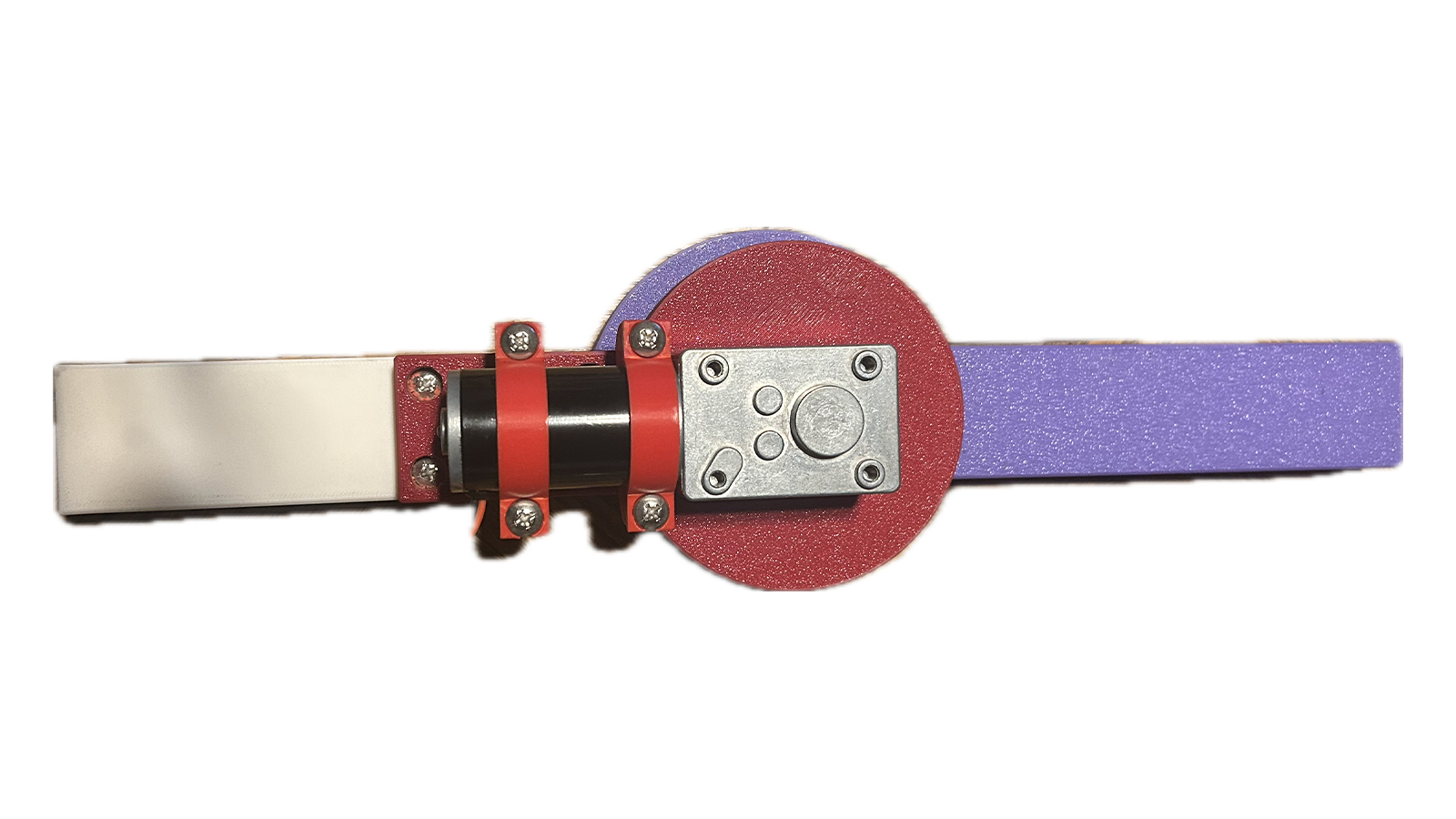
LawnBa
Team Members
- Thomas Gokie
- Benedict Ringer
- Jordan Gartner
- Austin Hill
- Jared Ganshorn
Overview
LawnBa is an autonomous lawn watering robot system, composed of a motorized reel and a self-driving robot sprinkler. The user defines an area desired to water by a web application through Google Maps. The program then calculates the path for the robot to effectively water the entire defined area. A custom path-smoothing program helps to prevent the hose from snagging while driving. The robot is equipped with GPS to correct errors while driving.
The sprinkler resembles a tractor robot with spinning arms to dispense the water. There are three custom PCBs on the robot – two stepper motor drivers and a RP2040-based microcontroller board. The reel is powered with AC from a receptacle and communicates to the robot with Wi-Fi. A raspberry Pi on the reel hosts the website and the main program.
Pi-casso
Team Members
Mason Mandernach
Collin Glover
Dawson McGahan
Guenther Switzer
Vince Mendick
Overview
In engineering education, diagrams are an essential tool for visually communicating complex concepts from mathematical functions to circuit layouts and free-body diagrams. Traditionally, these are drawn by hand on a whiteboard, leaving diagram quality entirely dependent on the artistic ability of the instructor. Inconsistent or unclear drawings can hinder student understanding, and recreating complex diagrams repeatedly wastes valuable class time. Our group set out to solve this with Pi-casso, an automated whiteboard drawing robot designed for the modern classroom. Pi-casso uses a cable-driven mechanism consisting of two stepper motors connected via cables to a central toolhead that holds a dry-erase marker. By precisely controlling the tension and length of each cable, the system can position the toolhead anywhere on the whiteboard surface and draw with repeatable, consistent accuracy. The motors are controlled by an STM32 microcontroller, which receives commands from a Raspberry Pi running a custom graphical user interface. Through this GUI, an instructor can upload an image, sketch something directly on screen, or select a preset, and Pi-casso will replicate it on the whiteboard in physical marker lines.
What sets Pi-casso apart from alternatives like projectors or smart boards is its simplicity and portability. Rather than projecting light that washes out in bright rooms or requiring expensive fixed installations, Pi-casso produces real, physical marker lines directly on the board just like an instructor would, but with precision. The system mounts entirely via suction cups, requiring no permanent hardware or modification to the whiteboard or classroom. This makes it adaptable to virtually any standard whiteboard size and easy to set up or move between rooms. Pi-casso bridges the gap between hand-drawn flexibility and the accuracy of digital tools, giving instructors a practical, affordable way to bring cleaner, more consistent diagrams to the classroom.
Smart Power Strip

Team Members
- Adam Sauer
- Calder Obal
- Jacob Ashman
- Trey Hasenkamp
Overview
Our project is a smart power strip that will be connected to a central hub by Bluetooth. The central hub will be able to have multiple connections to different smart power strips that a user might have in their home. The power strip will have 3 outlets where each one will have a voltage and current reading that will be able to be read from an online website. The central hub will have a raspberry pi that will read the information from the smart power strip and transmit it to the website which the user will be able to read and manage their power strip. Controls can vary from timers on certain outlets to turning off and on outlets. There will be a rsp240 in the power strip that will be the method on how the power strip will communicate with the raspberry pi. The power strip will have the main power cord taken from a power strip and its casing be 3D printed to properly house our board. There will also be an LED screen on the outlet to also show the values gotten from the board. It will also be the main way to connect the power strip and the central hub.
Solar Charge Controller for Multiple Battery Types
Team Members
- Kaleb Reiser
- Elizabeth Westfahl
- Cole DeBoer
- Justin Keegan
- Chloe Holmes
Overview
Our project deals with the design and development of a solar charge controller that is able to support multiple battery types. Powered with the use of solar panels, the charge controller is able to safely charge multiple battery types based on their specific requirements. The charge controller’s system is built with the use of a custom-designed printed circuit bo ard, Raspberry Pi 4, touch screen display, and supporting circuitry. These components work together to monitor and control the charging process. The screen allows for users to input the required battery parameters such as, voltage, milliamp hours, and type, as well as display the state of charge and voltage of the battery currently being charged. Based on the input, the charge controller adjusts its charging profile for the safe charging of each battery type. This project is designed to make charging any battery with any solar panel user-friendly for everyone to easily use.
The Gauntlet
Team Members
- Grant Ross
- Paul Powell
- Eli Larson
- Ben Greiner
- Diego Espinoza
Overview
The Gauntlet is a wearable glove-based system designed to capture and wirelessly send hand motion, orientation, and finger articulation data for gesture recognition and control applications. Currently its setup for simple American Sign Language translation. Major development areas include a: Custom PCB Control board and battery management system, custom PCB MIFA bluetooth antenna, custom python machine learning model, implementation of wearable conductive fabric, and use of the Nordic nRF52810 microcontroller.