Mechanical & Materials Engineering
3D Polymer Welding
Team Members
- Levi Kicken
- Jonathan Haag
- Seth Harsh
- Norval Books
- Isaac Beacom
Overview
Additive manufacturing adoption has rapidly accelerated the development and deployment of 3D-printed pressure vessels across a wide range of industries. These vessels, often produced from engineering polymers such as PA12, offer significant advantages in weight reduction, geometric flexibility, rapid iteration, and cost-effective prototyping. With modern powder-bed fusion systems, thin-walled pressure vessels can be fabricated either as monolithic components or as multi-part assemblies, and Honeywell’s experiments have demonstrated pressure vessels withstanding internal pressures exceeding 200 psi with minimal wall thicknesses.
However, the fabrication of multi-component pressure vessels remains a notable challenge. When pressure vessels cannot be printed as a single piece, multiple joining strategies must be considered. Common assembly methods such as mechanical fastening, threaded interfaces, and various bonding techniques have demonstrated limitations for use in pressure vessels. To address these shortcomings, the exploration of alternative joining methods is essential. Among these, polymer welding techniques represent a promising solution for creating strong, continuous bonds between printed components. Yet, despite its potential, the optimal welding parameters for additively manufactured PA12 are not well defined in current literature. The interaction between the microstructure of printed PA12, with its anisotropic mechanical properties, and the application of welding procedures introduces additional complexity not present in conventionally manufactured polymers.
For these reasons, there is a critical need to systematically investigate and characterize welding techniques for 3D printed PA12 pressure vessels. Establishing a controlled, repeatable welding process will help enable reliable multi-component vessel manufacturing and assembly for engineering applications.
Baja SAE Tube Bender Design

Team Members
- Leonardo Ruiz-Juvera
- Brandon Le
- Thoai Lu
- Treyson Johnstone
Overview
Our groups Mechanical Engineering Senior Design Capstone Project focuses on repairing and improving the current Baja SAE tube bender. For a while now the Baja team has wanted a means to bed their tubing in-house, as currently they must outsource their bending. Having this flexibility will allow the team to create and test more prototypes throughout the season, improving their designs. In previous years the Baja team purchased a tube bender and mounted it to a vertical fixture which quickly broke after its first use. This year’s project focuses on repairing the existing tube bender, enabling the pneumatic cylinder, and creating a new fixture for the team to use with the bender. Some design aspects requested are that the team wishes to make multiplane bends and wishes for it to mount to multiple tables as it will move around a lot. Design constraints include using the existing tube bender, maintaining a similar footprint as the previous tube bender, and a design that can be transported and loaded onto a trailer by two people. The group tackled this design by creating a flat fixture with tabs to be able to clamp onto any table and slots to mount to fixture tables. The frame can be mounted on the existing fixture cart to aid with transport and storage of the bender. Multiple parts were ordered to repair and improve the tube bender design. In conclusion, our group was able to re-design the previous tube bender fixture to meet the Baja team’s needs while improving their existing design to save on costs and prevent future breakdowns.
Cislune – Low Pressure Vacuum Chamber
Team Members
- Hank Battistoni
- Gunnar Nyberg
- Keegen Reynolds
Overview
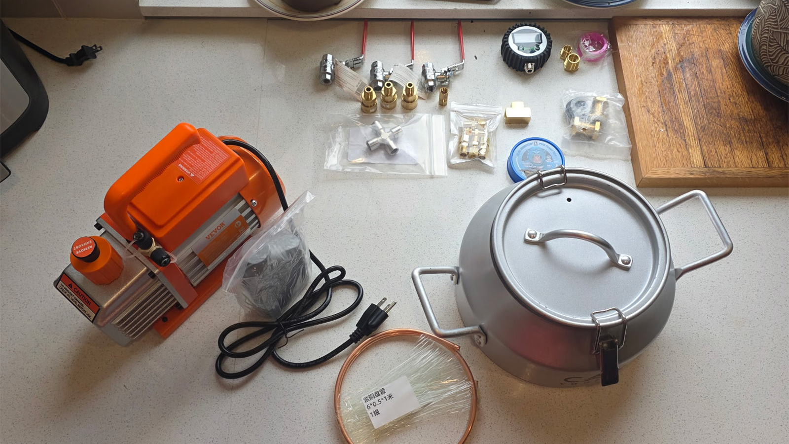
Many gasket and seal materials used in mechanical systems must operate in low-pressure or vacuum environments, where even small leaks can significantly affect system performance. Currently, there is no simple, low-cost testing apparatus available in the laboratory to evaluate leak-by behavior of sealing materials under controlled vacuum conditions.
As a result, students and researchers lack a practical way to experimentally study how different gasket materials perform when subjected to pressure differentials typical of low-pressure systems.
The goal of this project is to design and construct a low-pressure vacuum chamber capable of performing leak-by tests on gasket materials. The chamber will allow users to evacuate air to a specified pressure (≈300 Torr or lower) and measure leakage behavior through controlled instrumentation including vacuum gauges, valves, and pump connections.
Cislune – Vacuum Chamber Data Acquisition System
Team Members
- Karson Swartzbaugh
- Caleb Calafiore
Overview
Long before Artemis II launched earlier this month, years of work went into building up the commercial and civil space engineering capabilities for such an astronomical feat. As part of the Artemis program, a sustained lunar presence with permanent human habitation and reusable rocket pads alike are planned throughout the 2030’s. This will require new technology and techniques to start building a sustained lunar presence from the ground up, on a very fine and dusty lunar surface composed of regolith. Cislune is our sponsor from Rosemead, California, who works on NASA SBIR/STTR contracts relating to regolith technology. Projects like their GRASP project will demonstrate a compacted regolith landing pad and surrounding berm for the Artemis program. To validate their technologies, Cislune requires a high-vacuum pressure chamber to conduct tests inside. Our group was initially tasked with developing an entire pressure chamber system until the scope in the second semester was refined to the data-acquisition (DAQ) capabilities needed for such a system. We completed an analysis of our options, developed a bill of materials based on the selected DAQ design, and refined a design to hand off to Cislune.
Given the complexity of such a system, a framework was created and followed for the design of the DAQ system. This framework applies to future development of the system and involved the development of a concept of operations for the system with operational configurations of the system, a system hierarchy based on the operational procedures, interfacing between the system components and external components, requirements for a successfully designed system, trackable and quantifiable technical performance metrics for the duration of system design, fail case and risk management of the design, verification & validation testing for confirmingr equirements have been met, and more on the systems engineering process. The systems engineering focus for this complex and dangerous system was undertaken to enable future individuals on this project to complete building a high-vacuum pressure chamber. This systemic focus was in tandem with problem definition, design decision matrices, budgetary management, timeline management, and the other standard steps seen for other senior design projects.
Conveyor System for Portable Industrial Robot (Astorino)
Team Members
- Preston Pinkelman
- Mario Mora
- Nolan Quintanilla
- Fermin Moreno Jr
- Caleb Smith
Overview
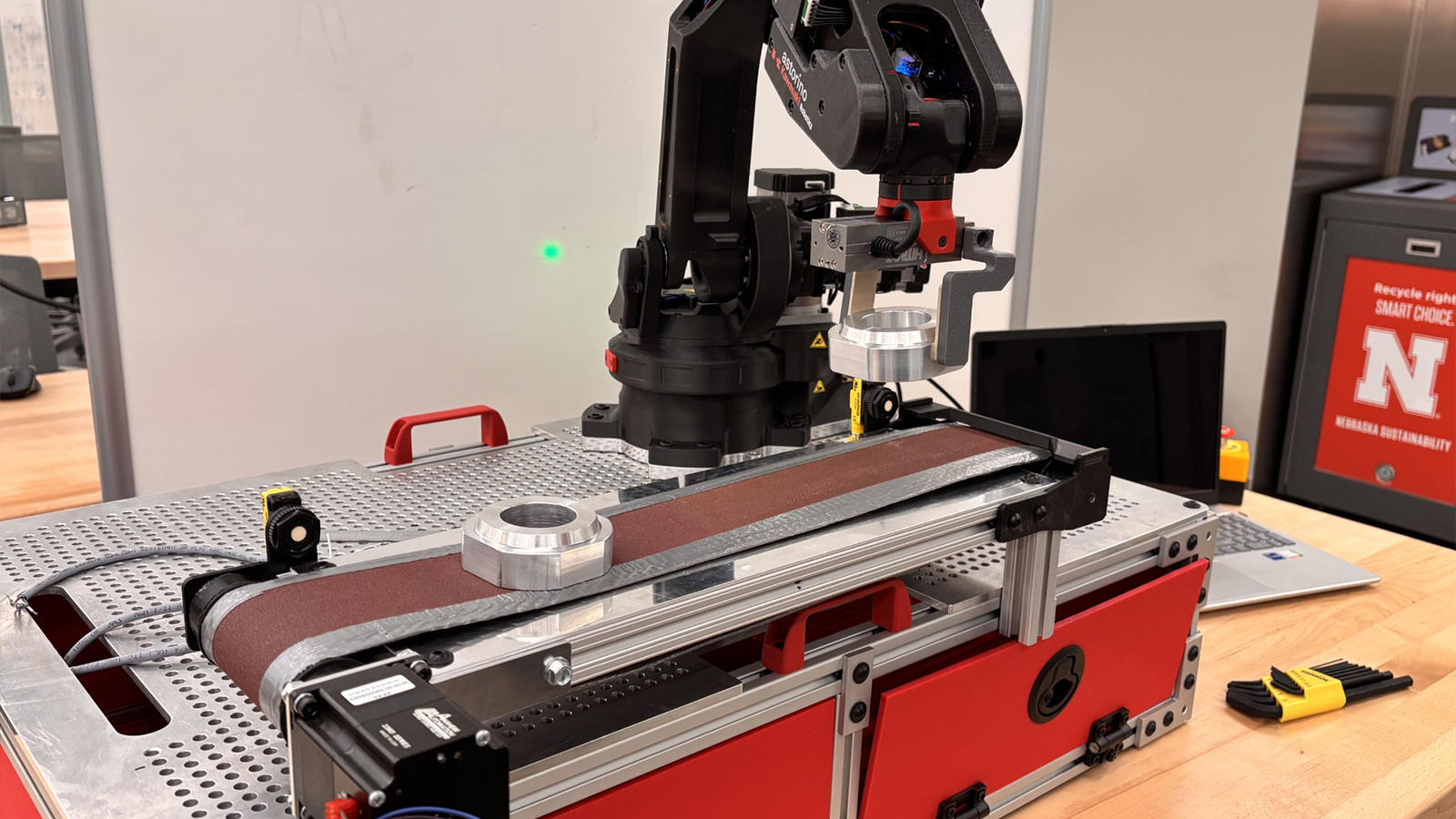
This project involves the design and construction of a portable conveyor belt system to interact with a provided educational robot to utilize for showcases.
Kawasaki in Lincoln has a portable robot called Astorino that they use for various showcases and activities; some programmed activities include placing a basketball in a hoop and rearranging aluminum pucks into a pallet region. Kawasaki wants to extend the functionality of the robot by adding a conveyor belt that can carry aluminum pucks and interact with the robot to run programs.
The conveyor system is built on a sturdy frame using 80/20 aluminum beams, which allows it to easily interface with the mounting plate of the robot. Each end of the conveyor has 3D printed rollers made of PETG-HF material for its superior load-bearing properties. A polished aluminum plate sits on top of the frame to support any objects traveling on the conveyor belt, and a stepper motor is installed on one of the rollers to allow for precise movements. This design uses easily repairable and replaceable parts to allow for simple diagnosis of any issues that may arise. Additionally, parts have been redesigned to be as safe and effective as possible, covering any possible pinch points and easily carrying any feasible load exerted onto the design.
The robot uses a variety of electrical components, namely a stepper motor, two ultrasonic sensors, and an arduino board. This arduino board can be endlessly reprogrammed by using the sensors as inputs and the motor as an output. Additionally, the functionality of arduino allows it to call functions on the robot, so the conveyor belt’s sensors will be able to tell the robot to run a program. This allows for a more in-depth interaction between the robot and the conveyor system.
Ultimately, this conveyor system aims to provide more functionality to and interaction with the Astorino robot while remaining portable and efficient. The capacity for this conveyor to interface with both the mounting plate and the robot should lend itself to a variety of new functionality in its showcasing years to come.
Crop Production in Space
Team Members
- Grace Fredrickson
- Khanh Le
- Kaita Baird
- Peter Lux
- Blake Waring
- Ryan Brost
- Gael Perez Alvarez
Overview
The University of Nebraska-Lincoln requires all senior mechanical engineering students to complete a capstone project in collaboration with an industry partner and a faculty member. Each team is tasked with solving a real-world engineering problem defined by the client, working under faculty guidance to develop a validated, professional solution. The team is partnered with NASA’s Jet Propulsion Laboratory (JPL) and Virtual Incision (VI) to advance sustainable crop production technologies for long-duration space missions. The team consists of six undergraduate mechanical engineering students of various backgrounds; one undergraduate electrical engineering student; Dr. Shane Farritor, David B. and Nancy K. Lederer Professor of Engineering and founder of VI; and Ryan Mccormick, an engineer at JPL. Per the capstone requirements in May, the team will present a poster at a symposium covering the finished product, showing proof that the team was successful. The team’s project focused on redesigning the end effector of VI’s MIRA, a surgical robot, to enable delicate teleoperated plant handling and autonomous plant anomaly detection through a computer vision system in microgravity environments. The primary objective was to develop a modified gripper capable of manipulating and cutting plants without causing visible or structural damage. The design utilizes MIRA’s surgical precision and compact build to maximize mobility in Ohalo III and features a coated gripper with a compliant polymer interface to minimize damage. In parallel, the team developed a computer vision system integrating an Arducam 12MP 477P Motorized camera with Pan/Tilt servo actuators.
Eddy Current Engine Dyno
Team Members
- Zach McArthur
- Curtis Krause
- Faith Petersen
- Payton Mitchell
Overview
This project supports the Husker Motorsports Formula SAE team by creating an engine dynamometer capable of applying load directly to the output of an engine. The goal of this project was to enable the team to derive horsepower and torque data of an engine from a single RPM pass as well as providing increased engine tunability.
This system utilizes eddy currents acting through dual spinning aluminum discs to provide resistance to an engine. This system is controlled by a custom current regulating circuit to determine the resisting torque. This circuit utilizes Load Cell, Wheel Speed, and Temperature measurements to ensure safe and proper operation.
Electromagnetic Crane & Wind Vehicles
Team Members
- Hayley Hogan
- Eddie Morrissette
- Calvin Dao
Overview
This project involves the design of two interactive STEM exhibits for the Strategic Air Command (SAC) & Aerospace Museum. It’s aimed at engaging 4th-8th grade students through hands-on learning. The exhibits were created for the museum’s Star Wars themed “Unofficial Galaxies” event, where students rotate through stations. The goal of this project is to engage students while introducing key STEAM concepts through experiential learning.
The first exhibit is an Electromagnetic Gantry Crane, designed to demonstrate the concept of magnetism and motion. This system uses a three-axis (XYZ) gantry mechanism driven by stepper motors and controlled by an Arduino. Students interact with the crane using simple controls to move an electromagnet and pick up lightweight objects, demonstrating principles of electromagnetism, motion control, and degrees of freedom. A CoreXY configuration was selected for the gantry. This configuration makes it beneficial for repeated use in a high-traffic educational setting. The crane is enclosed to ensure safety and is designed to withstand continuous interaction from groups of children.
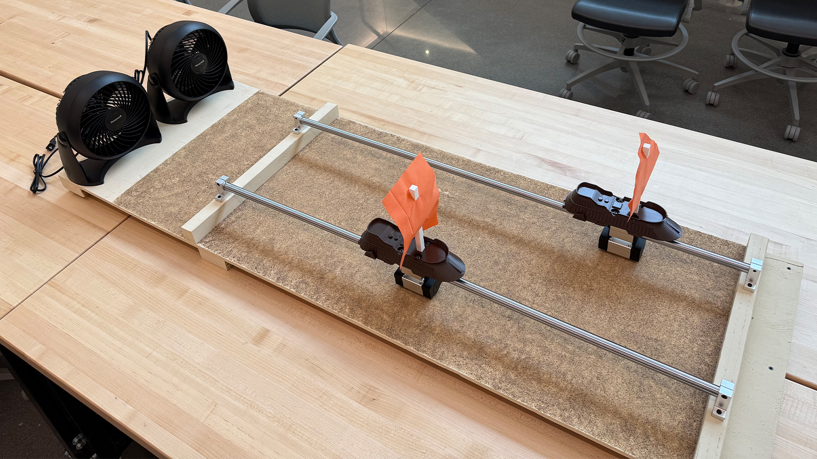
The second exhibit, Wind Vehicles, introduces students to basic fluid mechanics and aerodynamics. In this activity, students race small sail-powered vehicles modeled after the Star Wars “Khetanna.” The vehicles travel along a guided rail system and are propelled by wind generated from fans. Students can experiment with different sail shapes to observe how design influences speed and performance. A pair of linear guide rails with a circular profile were selected to ensure stability, alignment, and durability under frequent use.
Both exhibits are designed to be highly interactive, durable, and easy to use within a short time frame. They are also meant to be used by multiple children at one time. The designs prioritize safety, reliability, and resistance to misuse, with protective enclosures and robust materials incorporated throughout. Overall, this project delivers two engaging, Star Wars-themed educational stations that align with the SAC Museum’s mission to promote STEM learning.
Fowling Warehouse Net Design
Team Members
- Vinny Cacioppo
- Frank Curran
- Evan Hill
- Cooper Swoboda
Overview
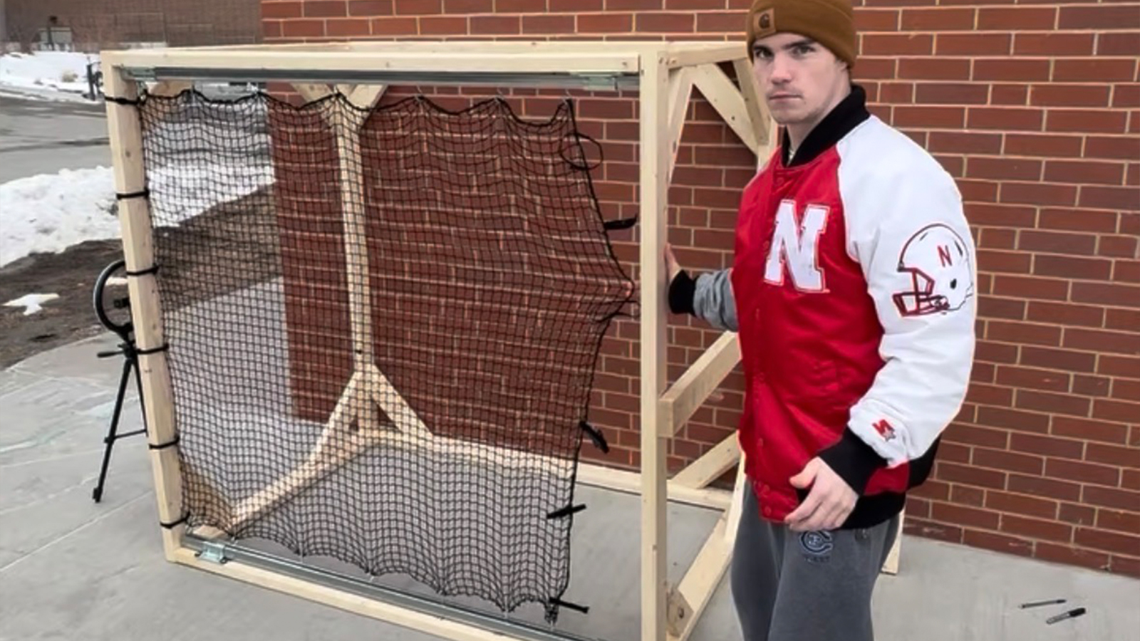
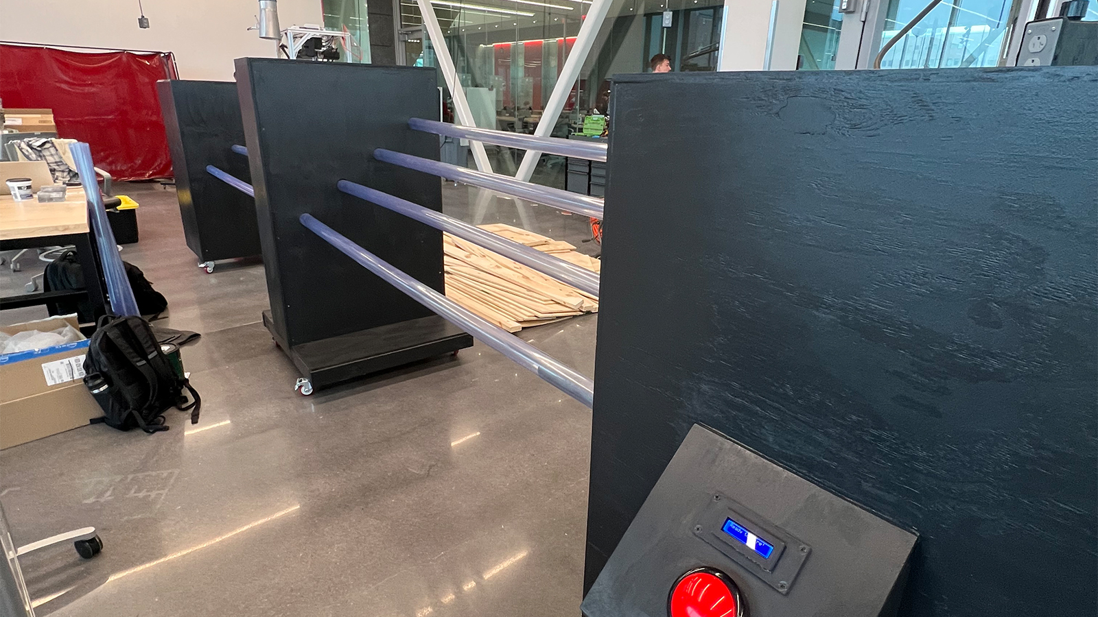
Fowling is the abbreviation for the yard game “Football Bowling.” Fowling Warehouse is a Midwestern-based franchise that houses lanes and event spaces centered around this game. The Fowling Warehouse of Omaha is currently fitted with many panels of stationary netting to protect the game playing areas and keep any footballs from entering the main walkways. The purpose of this project is to fulfill ownership’s desire to quickly remove the netting in order to host non-Fowling related events in the space. The nets are very large and obstruct almost every view across the building. If there was a speaker or presentation, it would not be very enjoyable for those behind a net.
Our team’s goal is to alter the current nets so that Fowling Warehouse staff can quickly remove them if any event is going on. The nets must be equally easy to reinstall after said event is over.The system we designed acts similarly to a sliding door with tracks and ball bearing on the top and bottom of the nets. After the nets are detached from the main structural frame, it is easy to drag them into the open position. We delivered a fully functional half-scale prototype, testing confirmations, part drawings, and instructions for how to alter the existing nets.
Husker Motorsports Active Aerodynamic System
Team Members
- Daniel Brajic
- Djamel Ba
- Michael Franzen
- Isaiah Balcom
Overview
Each year over 120 teams from universities across the U.S. and the world gather at Michigan Speedway to compete in various dynamic events in their student designed formula style race car. Part of each design may include an aerodynamics package which utilizes airfoils, wings, and other aerodynamic devices to produce downforce on the tires. Downforce is essential to put more normal force on the tires at a minimal weight penalty. The cost of producing downforce is drag force which acts against the forward motion of the car, slowing it down on straights and lowering its fuel efficiency. A active aerodynamic system solves this by allowing the wings to be adjusted on the fly using an spar and linkage system powered by electronic servo motors. The system can move the wing elements to varying angles of attack, lowering the drag force felt and allowing for live tuning of driving dynamics in a turn. It is programmed to be adjustable based on driver and vehicle inputs such as steering angle, vehicle velocity and throttle position.
Impact Attenuation of 3D Printed Structures
Team Members
- Noah Ference
- Luke Schwaninger
- Camden McMahon
- Matt Buhlmann
- Rayden Thompson
Overview
The goal of this project was to design a fully 3D printed structure that could protect an egg when dropped from a height of 8 feet. The printer used for the project was an HP Multi-jet Fusion printer that Honeywell has in their Kansas City National Security Campus. The design had to fit within a 5” cubed area and be composed only of 3D printed Nylon-12 material.
Interactive Baseball and Tennis Simulator
Team Members
- Victor Loma
- Austin Ronspies
- Thomas Hakonson
- Kory Sykora
Overview
This project focuses on the design and development of an adaptive tennis and baseball simulator bay for MSForward, a wellness center that supports individuals with multiple sclerosis and other neurological conditions. The goal is to create a safe, accessible, and engaging environment that encourages physical activity and recreation for users with a wide range of mobility levels.
Currently, the tennis and baseball setup at MSForward consists of a simple tee and net system with limited structure and minimal interactivity. This project aims to significantly improve that experience by designing and constructing a dedicated simulator bay that enhances safety, usability, and overall engagement. Unlike more advanced simulation systems, this design does not include ball tracking or automated scoring. Instead, it focuses on creating a reliable physical environment paired with a simple, intuitive visual scoring system.
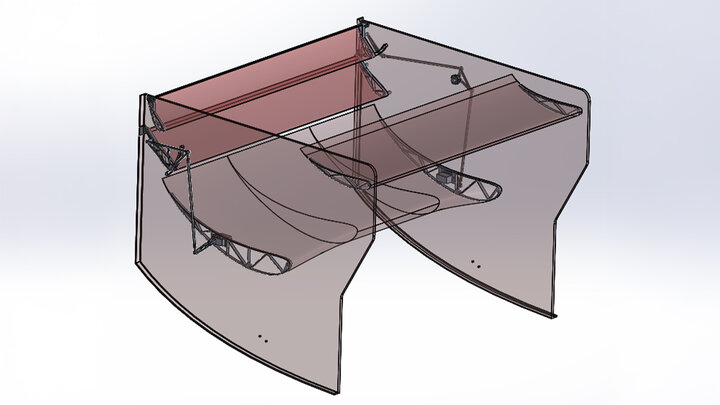
The core of the design is a fully enclosed bay built using an aluminum frame with netting on the sides, back, and ceiling. This enclosure ensures that all balls, whether hit cleanly or missed, are contained within the space, reducing risk and making the system more user- friendly for individuals with limited coordination or strength. The structure is designed with accessibility as a priority, allowing use from both standing and seated positions, including wheelchair users. Entry and exit points are kept clear, and all components are arranged to minimize tripping hazards and obstructions.
At the front of the bay, an impact-resistant projection screen is mounted to the frame. A projector displays a still image of a tennis court or baseball field onto the screen, with clearly defined scoring zones. Users aim for these zones when hitting the ball, providing a simple and engaging way to track performance without the need for complex electronics or software. This approach keeps the system easy to use, cost-effective, and reliable while still delivering an enjoyable experience.
Additional features of the design include a gravity-fed ball return system, which allows balls to roll back to the hitting area after impact, improving efficiency and reducing the need for manual retrieval. The frame is also designed to be modular and partially collapsible, allowing the system to be moved or stored as needed within the facility.
The project is developed under several constraints, including a fixed budget, limited indoor space, and the requirement to meet accessibility standards for individuals with neurological conditions. Emphasis is placed on durability, simplicity, and ease of use to ensure the final product can be reliably used by both clients and staff.
Ultimately, this project delivers a practical and inclusive simulator bay that enhances one of MSForward’s most popular activity stations. By prioritizing safety, accessibility, and user engagement, the design provides a meaningful improvement to the existing setup while laying a foundation for potential future technological upgrades.
Ion Wind Rotor Start Kart and Paper Circuits Droid
Team Members
- Matthew Moy
- Dylan Filipi
- Michael Williams
- Stephanie Ryle
Overview
Our senior design project was to build two stations for students to visit and learn at the SAC museum spring classroom sessions. One was to utilize a vandegraaf machine provided by the museum, and the other to incorporate electrical circuits. With these prompts and some guidance from the museum, as well as the design and engineering processes, we created the Ion Wind Rotor Start Kart and the Paper Circuits Droid.
These stations were constructed in the Kiewit Hall Large Project room on the ground floor, using the 3D printers and woodshop and on-site experts. Our team brought these structures together with the instruction and guidance of our instructor Kurt Palik as well as the education team at the SAC museum. Both structures were delivered functioning and on-time and under budget by the deadline of January 1st. Ongoing improvements and maintenance of these stations have been in progress all spring, and we are proud to present our finished work at the Senior Design Showcase.
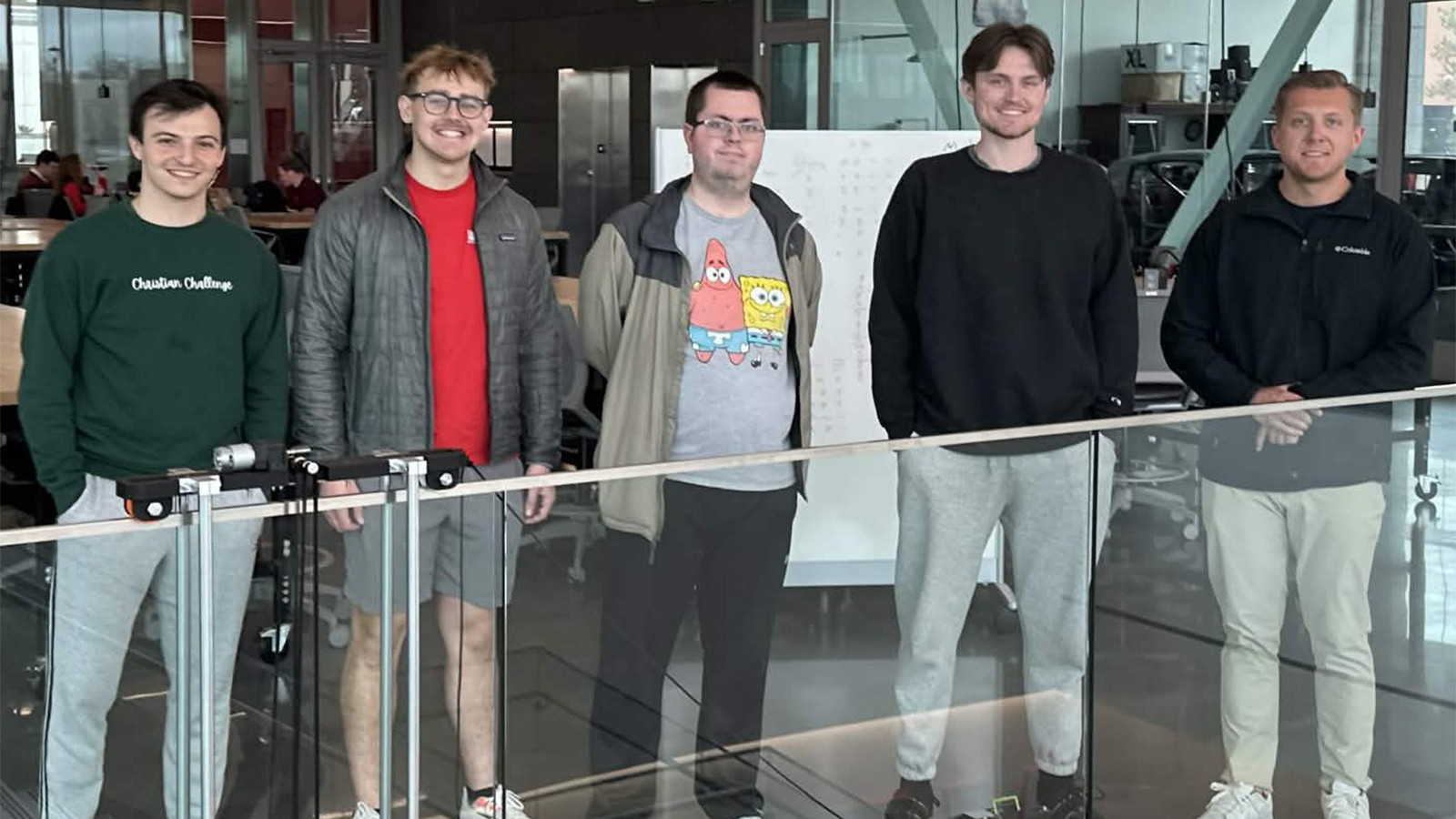
Kiewit Hall Rail Cleaning Robot
Team Members
- Cody Hora
- Cory Grieb
- Josh Freed
- Ethan Galusha
Overview
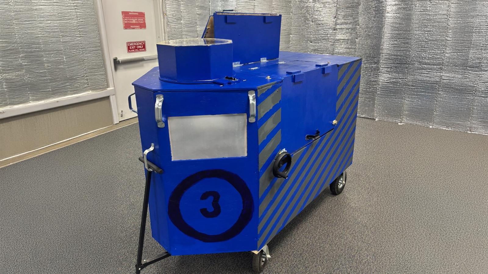
This project aims to design and develop an automated, cost-effective robotic system to clean the glass railings in Kiewit Hall at the University of Nebraska–Lincoln. Currently, the College of Engineering spends approximately $30,000 annually on manual cleaning services, which has prompted the need for a more efficient and sustainable solution. The proposed system will address routine cosmetic blemishes such as smudges and fingerprints while reducing labor costs and improving consistency and frequency in cleaning performance.
The primary objective is to create a robot capable of traversing straight sections of glass railing up to approximately 50 meters and completing at least one full, unassisted cleaning cycle per continuous railing section (excluding staircases). The robot must remove approximately 90% of visible blemishes on a single charge or fluid fill. Additionally, the system will incorporate sensing capabilities that allow for autonomous operation, including start-stop functionality based on position or environmental input. To ensure ease of use, the system is designed to require no more than four actions from janitorial staff: placing the robot on the railing, charging or refilling it, initiating operation, and removing it after completion of a cycle.
Several constraints guide the design. The robot must remain securely attached to the glass railing without causing damage or leaving permanent markings. It must operate at a noise level comparable to standard floor-cleaning robots (approximately 70 dB) and function effectively across varying railing heights. Furthermore, the cleaning solution must be controlled to prevent dripping or condensation onto lower floors, ensuring safety and cleanliness throughout the building.
To inform the design, a review of existing glass-cleaning robotic systems was conducted to identify effective mechanisms and best practices. Based on this research, a gantry-style system with a sprayer combined with a wiping pad cleaning method was selected as the most suitable approach. Input from Kiewit Hall janitorial staff indicated that water alone is sufficient for cleaning the targeted blemishes, simplifying the fluid system design.
The design process was organized into four main subsystems: rail traversal, cleaning method, supply method, and data intake. Multiple design concepts were evaluated using decision matrices, with six traversal methods, seven cleaning approaches, three supply systems, and three sensing strategies considered. The final design consists of a “Buddy Bot” drive system (containing cleaning solution, pumps, controllers, and driving motors/wheels) that pulls a cleaning module along the railing using distributed force via O-rings. The cleaning mechanism employs a vertical wiping pad controlled by a pulley paired with a controlled spray system, while the bulk of the system’s weight and power components are housed in the Buddy Bot. Sensor integration allows the robot to track its position and operate autonomously.
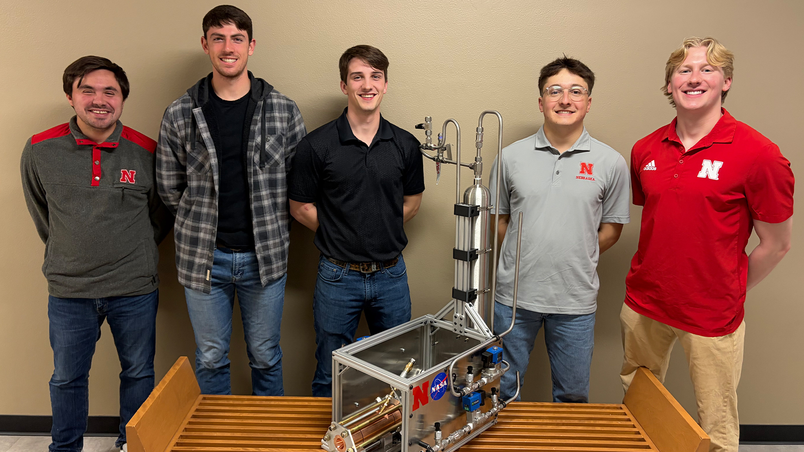
Liquid Ethanol / Nitrous Oxide Rocket Motor
Team Members
- Ryan Booth
- Jacob Imig
- Blake Johnson
- Vince Orsi
Overview
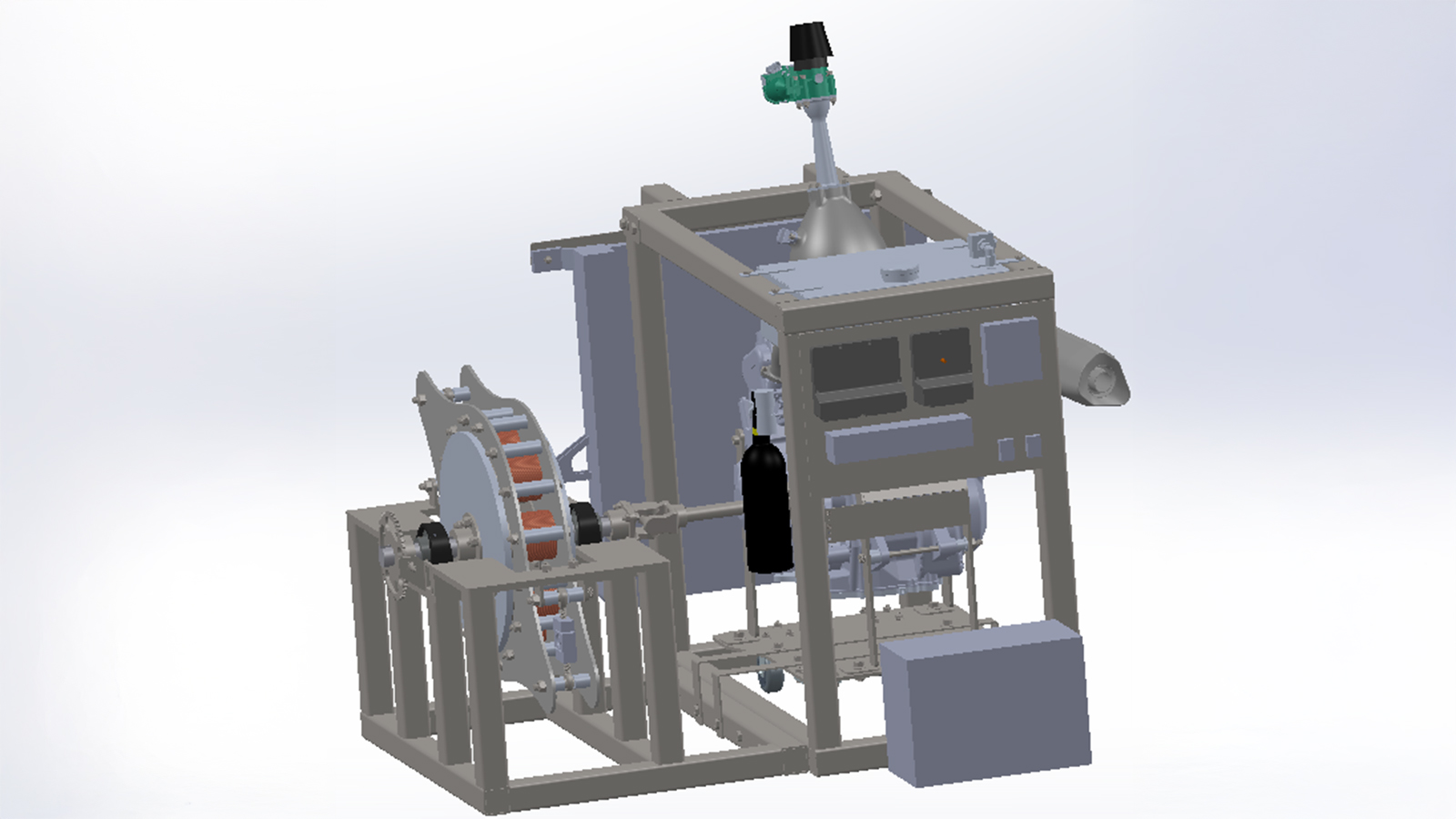
The world as we know is changing and changing fast. For the National Aeronautics and Space Administration to keep the nation at the forefront of critical technologies, public universities must continue to provide unique sources of innovation and skill development opportunities critical to our nation. The priority to develop interest in propulsion remains a key driver in these efforts, paving the way for the next generation of innovative engineers. To become a key player in this critical field, the University of Nebraska-Lincoln has undergone the development effort of its first liquid bipropellant rocket engine. With the power of off shelf propellants and local industry, this project is laying the groundwork to design, fabricate, and build a functional pressure-fed ethanol and nitrous propulsion system. The goal is to bring advanced propulsion to the talents of Nebraska’s College of Engineering and gain recognition in the International Rocket Engineering Competition with UNL’s Rocket Propulsion Group.
Our team is developing a pressure-fed bipropellant Liquid Rocket Motor. The team has designed, simulated, and tested a system specifically built for the University of Nebraska—Lincoln’s Aerospace Club Competitions. This effort further develops capabilities to support NASA’s future propulsion initiatives and paves the way for future propulsion programs at the University of Nebraska. The overarching goal is to develop advanced propulsion capability, interest, and required know-how at the University of Nebraska-Lincoln, creating a novel research avenue for the University.
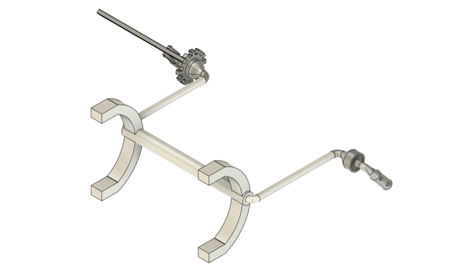
Micro-g Adjustable Tool Cart Handle
Team Members
- Braden Roberts
- Noah Lundak
- Cloud Roberts
- Frederick Wood
Overview
HANDLE (Haul Assisting Notched Dust-resistant Leverage Enhancer) is an adjustable tool cart handle that can assist astronauts in transporting equipment. Responding to this year’s NASA Micro-g NExT program challenge, it was designed to be attached to the existing NASA tool cart to make the cart adjustable to various heights, therefore allowing astronauts of all heights to comfortably use the cart. The design consists of 2 main parts: the adjustment mechanism and the handlebar. The adjustment mechanism is a lever that slots into a gear. The lever is laterally locked in place and held down using a spring. The spring ensures the lever will be pulled into the gear, preventing rotation, until it is pushed out of the way by the user. The adjustment mechanism is compatible with astronaut suit gloves due to limited pinch points, and incorporation of through-holes and covered bearings makes it tolerant to the potentially damaging lunar dust (regolith). Additionally, the handle position can be adjusted without any extra tools or disassembly. The handlebar resembles that of a bicycle and provides several ergonomic grip orientations to allow astronauts to push, pull, and quickly stop the tool cart when traversing the lunar surface. The handlebar is also large in diameter and smooth to prevent hand fatigue when wearing EVA (extra-vehicular activity) gloves. Overall, HANDLE is an inclusive design for astronauts of all sizes that ensures faster, easier access to tools during NASA missions. HANDLE saves time and energy by simplifying tool cart adjustments, therefore boosting the productivity of astronauts because they can spend more time focusing on scientific advancement on the lunar surface.
MSForward Cardio Machine Redesign
Team Members
- Josh Iossi
- Evan McDermott
- Israel Robledo
- Juntao Guo
Overview
This project focused on redesigning a cardio exercise machine for MSForward, an adaptive gym in Omaha, Nebraska for people affected by Multiple Sclerosis. The existing machine had problems with the resistance adjustment system and component durability. The objective was to develop a new lever for resistance adjustment, a mounting bracket for pin adjustment, and a protective enclosure around the chain system. The previous lever iteration interfered with users ability to utilize the machine effectively. The new design moves the lever out of the way of the user entirely while still allowing varying amounts of resistance. The lever is mounted on the brake and extended laterally to allow clear access and easy adjustment, improving the overall experience for the machine user.
The lever was constructed from a low carbon steel to match the existing machine frame. Analysis of forces aided in the selection of the thickness and geometry of both the lever and the bracket. The lever design considered the cyclic forces present with continuous use. Stress concentrations were also considered and minimized with appropriate dimensions and added support. With the lever, a mounting bracket was also constructed to allow for pin-slot locking at different resistance levels. This required very precise alignment to allow for smooth and effective resistance adjustment. SolidWorks modelling ensured the alignment was correct, while standard fasteners made assembly and maintenance easy. The protective box enclosed the chain system to prevent any injuries due to the close proximity to the brake. This protects both the volunteer adjusting the resistance for the user and the chain system from any debris. The housing was designed using 3D printers and mounted with simple fasteners, making it light and durable.
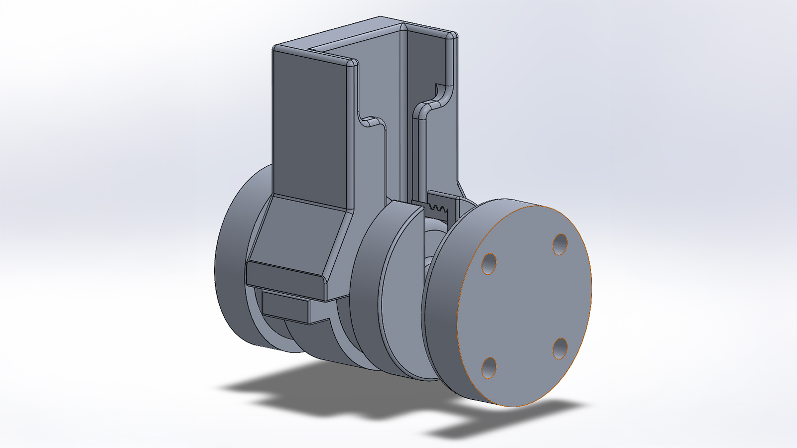
Muzzle Rise Eliminating Revolver
Team Members
- Joshua Wichman
- Victor Chan
- Jerry Hiles
Overview
Traditional handguns experience significant muzzle rise, which is amplified after consecutive rounds. This leads to decreased accuracy, safety, and increased risk of bystander injury.
There are existing designs in the market that aim to decrease this effect, but they center around reducing muzzle rise, either through slight configuration modification or using smaller caliber ammunition. However, these are simple fixes that ultimately have drawbacks. Smaller calibers carry less force. Modifying the current revolver configuration leads to uncomfortable ergonomics and major weight increase.
Our team intends to solve the issue of unwanted muzzle rise by completely eliminating it from the user experience. This will be done by not only lowering the firing axis, but bringing it perfectly in line with the user’s reaction through the grip. This requires a significant alteration of the classic revolver configuration, and so extensive engineering and design will be needed in order to actualize this design.
In addition to the muzzle rise elimination, our design seeks to decrease firearm frame profile and weight, while maintaining a similar shooting feel and ergonomics to a traditional revolver.
Felt recoil will also be absorbed and decreased, and our team will analyze the effects of this design’s recoil on the human body.
Once design is complete, our team will manufacture and test a prototype, and organize the necessary documents to file for a utility or design patent.
NASA Micro-G NExt Challenge 2 - PCAR
Team Members
- Zach Robeson
- Tyler Gaspers
- Andrew McNamara
- Kaleb Van Driel
Overview
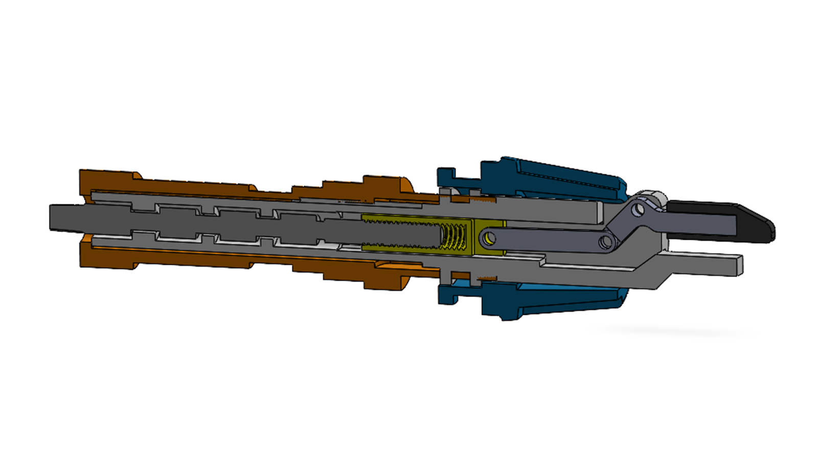
The PCAR (Passive Capture Active Release) is a tool docking mechanism developed to address the challenges astronauts face when securing tools during extravehicular activities (EVAs). In the microgravity environment of space, astronauts must manage tools efficiently while dealing with limited mobility, restricted visibility, and bulky pressurized gloves. Existing methods for tool retention can require excessive force, multiple steps, or visual confirmation, increasing both fatigue and risk. PCAR is designed to provide a simple, reliable, and safe solution that enables astronauts to dock and release tools quickly using only one hand, even without direct line of sight.
The system consists of two primary components: a male attachment fixed to the tool and a female docking assembly mounted to the astronaut’s suit or equipment. The docking process is entirely passive. As the male component is guided into the system through a T-channel, it engages with a spring-loaded angle block housed within a cylindrical chamber. The angled geometry of this block allows it to retract upon insertion, enabling the tool to slide into position. Once fully seated, the spring forces the block back into place, locking the tool securely without requiring additional action from the user.
To release the tool, PCAR incorporates an active, two-step mechanism that ensures single-fault tolerance. The astronaut must first push the tool inward, compressing the spring and retracting the locking block. This aligns the male component with the T-channel, allowing the tool to then be pulled free. This dual-action requirement prevents accidental release while still maintaining ease of use. The design prioritizes intuitive operation, making it suitable for use in high-stress, low-visibility environments.
PCAR is engineered to meet strict performance and safety requirements. The device weighs approximately 0.56 pounds and fits within a compact volume smaller than 3.5 inches in all dimensions. It is capable of supporting loads up to 25 pounds, exceeding the minimum requirement, and operates with an actuation force below 10 pounds-force. Structural analysis, including hand calculations and finite element analysis (FEA), confirms that the system achieves a factor of safety greater than 2.0 under expected loading conditions. The design uses corrosion-resistant and NASA approved materials, including 6061 aluminum, stainless steel, ABS, and TPU, ensuring durability and compatibility with neutral buoyancy testing environments.
Manufacturing of the PCAR system is optimized for accessibility and cost-effectiveness. Structural components are machined from aluminum stock using CNC equipment, while more complex geometries, such as the angle block, are produced through additive manufacturing. The modular design allows for easy assembly, maintenance, and potential iteration. A secondary design concept, incorporating flexible retention features, is available to enhance redundancy if required.
Overall, PCAR provides a lightweight, reliable, and user-friendly solution for tool docking in space applications. By reducing the effort required to secure and retrieve tools, the system enhances astronaut efficiency, safety, and mission performance during EVAs.
SAC Submersible
Team Members
- Will Brison
- Brandon Cervania
- Lane Knop
- Devon Shallberg
- Elijah Wilgus
Overview
The SAC Submersible is a Star Wars themed exhibit for children’s field trips. The submersible is 3D Printed Death Star that displays the principles of buoyancy force, which is controlled by hand-held controls.
Showerability
Team Members
- Luis Osorio
- Cameron Herrera
- Lexi Vohland
- Liam Crimmins
- Charleigh Schonlau
Overview
Patients undergoing low-mobility therapy run the danger of slipping, losing things, and getting tired when taking a shower. Showerability offers a magnetic shower board system that holds hygiene supplies at reachable heights, however the existing polyurethane wraps don't offer enough grip while wet and can't fit a variety of product sizes, which causes problems with usage and safety. The goal of this project is to increase grip, safety, and flexibility by redesigning the Showerability magnetic wrapping. Two designs will be included in the system: one for bigger objects like shampoo or soap bottles and another for smaller items like razors and toothbrushes. Durable, disinfectant- resistant materials that retain a non-slip grip in damp environments will be used in both designs. The bigger design must fit bottles up to 5.5 cm in diameter, and the wrapping must use magnets to connect to the shower board, the maximum magnetic field strength must be below 500 μT to avoid interference with pacemakers and it should hold at least 0.4 kg with an ultimate tensile strength equal or larger than 3 MPa.
Smart Physical Therapy Device
Team Members
- Mollie Petersen
- Lucas Sokolik
- Jacob Zitek
- Evie Collier
- Gracie Kniss
Overview
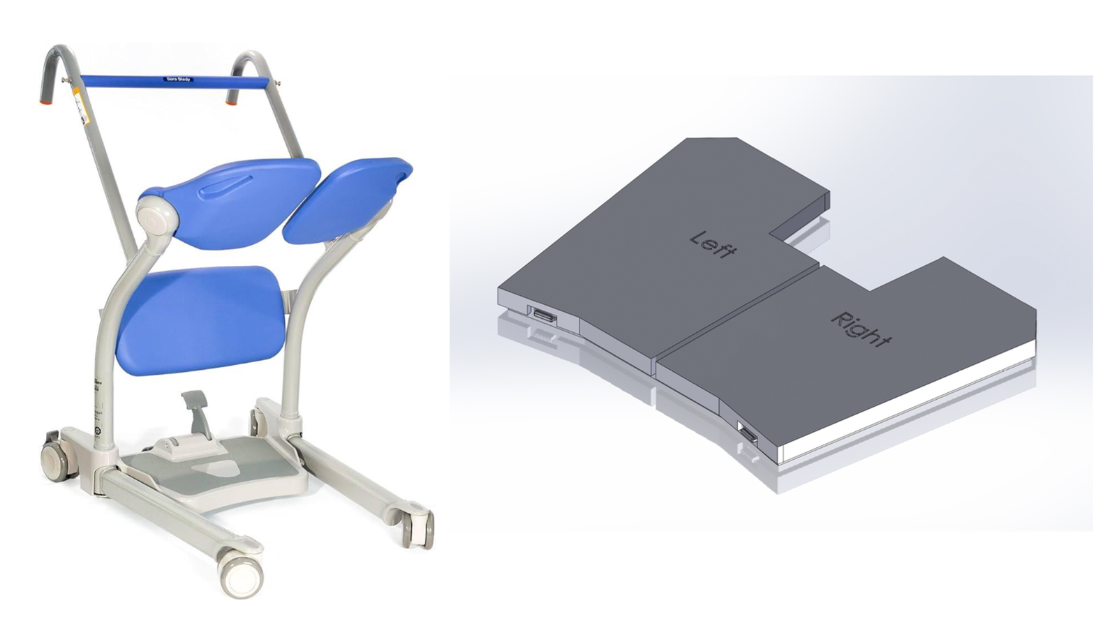
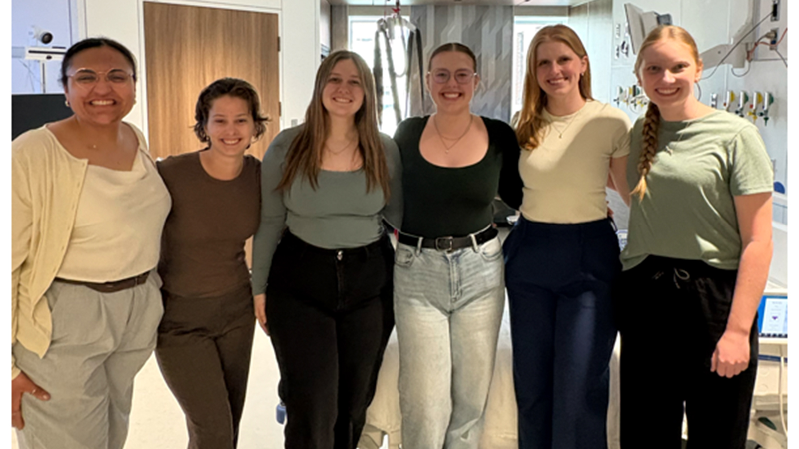
The Smart Physical Therapy Device is designed to improve how patients and physical therapists at the University of Nebraska Medical Center monitor weight distribution during rehabilitation using the Sara Stedy Sit-to-Stand. Traditional sit-to-stand equipment does not provide quantitative feedback, requiring therapists to rely on observation, manual notes, and patient-reported sensations to assess progress. This limits the ability to make precise, data-driven adjustments to therapy plans. Our project addresses this gap by developing a system that automatically measures and displays real-time weight distribution between the left and right sides of the body, enabling more informed clinical decisions and improved patient outcomes.
The device integrates directly onto the existing baseplate of the sit-to-stand equipment and is custom-designed using SolidWorks. The system consists of two foot platforms (left and right), each supported by two load cells, for a total of four sensors arranged similarly to a balance board configuration. These load cells continuously measure force distribution and send data to a processing unit, which outputs clear, real-time feedback on two LCD screens—one for the patient and one for the therapist. This setup allows both users to easily monitor symmetry and make immediate adjustments during sit-to-stand movements.
To support development, a miniature prototype using a single load cell was first created to validate sensor accuracy, wiring, and data collection. This testing phase informed the design and placement of the full four-sensor system. The full-scale prototype was then modeled to refine dimensions, optimize load cell placement, and ensure compatibility with the existing equipment. Physical testing and measurements were conducted on-site at UNMC using the Sara Stedy device to ensure proper fit and functionality.
The final prototype is designed to match the baseplate dimensions of the original equipment (12.25 inches in length, 17 inches in top width, and 15 inches in bottom width). It includes Velcro attachments for secure installation and a clamp-mounted display case positioned on the handlebars for easy visibility. The structure is 3D printed using ASA material to support patients up to 450 pounds while maintaining durability and cleanability required for a clinical environment.
Project constraints include a $500 budget and the requirement to maintain structural integrity without modifying the original equipment. The system must safely withstand patient loading without deformation or failure. Deliverables include a fully functional split-scale sensing system, dual display interface, and complete documentation.
SR-71 Blackbird Exhibit - Golf Ball Launcher
Team Members
- Gabe Sedlacek
- Austin Young
- Nate Zuroske
- Jeremy Pieters
- Charles Pittman
Overview
The SR-71 Blackbird exhibit is a golf ball launcher system that shows the difference in speeds between 4 aircraft. It works by firing 4 golf balls sequentially from slowest to fastest. The goal is to show museum patrons the incredible speed of the SR-71 Blackbird. The system works by firing a golf ball out of a cannon using compressed air. Each cannon is set to a specific pressure to shoot the golf ball at different speeds. The patrons would hit the fire button and the cannons begins firing the golf balls. The speeds of the golf balls are a representation of the aircraft speeds at a 1:20 ratio with the fastest golf ball traveling at 110 MPH. The golf balls travel through clear tubes so that the difference is speeds is easy to see.
Swing Builder
Team Members
- Julia Graves
- Julia Landauer
- Bryce Shurigar
- Katie Subiabre
- Hayley Witte
- Ved Patel
Overview
The Swing Builder project focuses on the mechanical redesign and performance optimization of a baseball/softball training device intended to improve swing mechanics through guided hip rotation and real-time feedback. The original system, while effective in demonstrating proper biomechanics, lacked portability, user adaptability, and accessibility for a diverse range of athletes. This redesign addresses those limitations by developing a compact, modular, and adjustable system that enhances both usability and performance tracking.
A primary goal of the redesigned Swing Builder is to improve user adaptability. The system incorporates adjustable resistance to simulate different swing loads, allowing athletes to train across a range of strength levels. Additionally, the device accommodates users between 4’6” and 6’8” in height, ensuring inclusivity across youth and adult players. This adaptability is critical for broadening the device’s applicability and making it suitable for team environments, training facilities, and individual use.
Portability is another key design focus. The redesigned system reduces both footprint and overall weight while maintaining structural integrity. The frame is engineered to break down into three main components, enabling easy transport and storage without requiring specialized tools. This feature directly addresses one of the primary shortcomings of the original design and makes the device more practical for real-world use.
To further enhance training effectiveness, the Swing Builder integrates real-time performance feedback using sensor technology. By incorporating the Ancore data plate, the system captures metrics such as hand speed, applied force, and velocity throughout the swing motion. This data enables athletes and coaches to quantitatively assess performance and make informed adjustments, bridging the gap between qualitative coaching and measurable results.
Preliminary testing validated the system’s ability to promote correct swing mechanics, particularly emphasizing proper hip rotation. Ongoing prototype testing compares the redesigned system to the original while leveraging sensor data to evaluate improvements. Overall, the Swing Builder redesign delivers a more portable, adaptable, and data-driven training solution that enhances athletic development while addressing key limitations of existing devices.
Tooth Pocket Depth Measurement Device
Team Members
- Carter Hogan
- Peyton Wuori
- Dalton Redding
Overview
Periodontal probing is used to measure the depth of the space between a tooth and the surrounding gum to assess gum disease. In current practice, this is done manually using a marked probe, where the hygienist inserts the probe and reads the depth by eye. This method depends heavily on technique and judgment. It can lead to inconsistent results between clinicians, and in some cases, readings may be exaggerated to justify treatment coverage from insurance providers. These issues highlight the need for a more consistent and objective measurement method.
The goal of this project is to develop an automatic periodontal probe that improves accuracy, repeatability, and data recording by using an integrated mechanical and electronic system. The device measures pocket depth using a miniature magnetic linear encoder, which tracks how far the probe tip moves as it is inserted into the gum. This displacement is converted directly into a digital measurement, removing the need for visual estimation.
To reduce variation caused by the user, the probe is designed to operate within a controlled force range of about 0.2 to 0.25 N, which is consistent with recommended probing force. Keeping the force consistent helps ensure that measurements are repeatable and not influenced by how hard the user presses.
A microcontroller processes the encoder signals and handles user inputs through a simple button interface. The user can record measurements, move between teeth, reset the probe position, and clear previous data. The measurements are sent to a computer interface, where they are organized by tooth and displayed in a format similar to standard dental charts. The interface also uses color coding to quickly show healthy, moderate, and severe pocket depths.
The mechanical design focuses on smooth linear motion and accurate alignment between the probe and sensor to ensure reliable measurements. The design also considers hygiene, with the ability to use a replaceable probe tip for sanitary use. On the electrical side, the system includes signal conditioning to ensure clean communication between components and accurate real-time data collection.
This project brings together mechanical design, embedded systems, and software to solve a real problem in dental diagnostics. By reducing user variability and providing digital measurements, the automatic periodontal probe can improve consistency, reduce the chance of inaccurate or misleading readings, and make record keeping more efficient. Future improvements would focus on refining the force control system, improving ergonomics, and preparing the design for potential clinical use.
UNMC Smart Inventory Tracking
Team Members
- Mustafa Almansouri
- Daniel Bischoff
- Olivia King
- Allen Virgen
Overview
The UNMC Inventory Tracking System project focuses on improving the inefficient manual restocking process of hospital supplies at the University of Nebraska Medical Center (UNMC). Currently, staff rely on visual inspection of supply bins, which can lead to delayed restocking, inconsistent inventory awareness, and increased labor demands. These inefficiencies may affect patient care and increase unnecessary costs. The goal of this project was to design a low-cost, scalable system that provides real-time inventory data and automatic alerts when supplies run low.
Several technologies were evaluated, including RFID tracking, computer vision, ultrasonic sensors, and weight-based sensing systems. Based on criteria such as cost, accuracy, scalability, and ease of integration, a weight-based system using Force Sensitive Resistors (FSRs) was selected as the most practical solution.
The final design uses FSR sensors placed beneath supply bins to detect changes in weight as items are added or removed. These sensors are connected through a prototype board using soldered resistors and wired directly to an ESP32 microcontroller. The ESP32 processes the sensor data and compares it to calibrated thresholds to determine inventory levels. When supplies fall below a set limit, the system triggers a low-inventory alert, allowing staff to restock proactively instead of relying on manual checks. Testing was conducted using various medical supplies to evaluate system performance. Results showed that the system can effectively detect changes in inventory levels. Overall, this project delivers a cost-effective and efficient solution that improves inventory tracking, reduces human error, and supports better patient care in hospital environments.
UNMC Table Moving Design
Team Members
- Blake Wyatt
- Ethan Wagner
- Leandro Castellanos Izaguirre
- Tandon Buhr
- Nate Bell
Overview
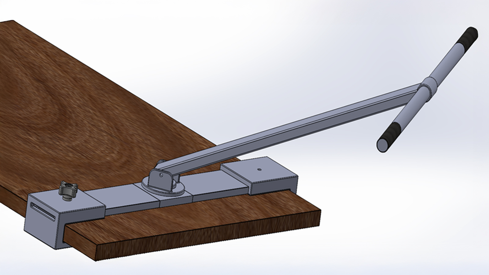
This senior design project, conducted through the University of Nebraska–Lincoln Department of Mechanical & Materials Engineering, addresses ergonomic and efficiency challenges faced by staff at the UNMC Innovation Design Unit when moving conference tables. The primary issues include excessive force required to unlock caster wheel brakes, awkward bending postures, limited control during movement, and inefficiency when relocating multiple tables.
The objective of this project is to design a non-invasive, cost-effective system that enables a single user to unlock and maneuver tables safely, efficiently, and without modifying or damaging existing equipment. The final design consists of a detachable handlebar system with integrated functionality for both mobility and brake disengagement. A clamp-based mounting mechanism secures the device to the table surface using rubberized pads to prevent slipping or damage. The handle assembly includes adjustable height and yaw rotation, allowing users of varying sizes to maintain ergonomic posture and full control during operation.
A key feature of the system is the wheel unlocker tool, which uses a molded groove and lever-cam mechanism to engage and release the caster brakes with reduced effort. This eliminates the need for bending and minimizes physical strain. The design was developed through concept generation, decision analysis, and SolidWorks modeling, with considerations for durability, safety, and ease of use.
With an estimated cost of approximately $276—well under the $500 budget—the solution remains economical while allowing room for prototyping and iteration. Overall, the design improves ergonomics, reduces labor demands, and significantly enhances the efficiency of table movement in real-world applications.
UNMC Walking Harness
Overview
The goal of this project was to design and prototype a better walking harness for Nebraska Medicine and UNMC. None of the current harnesses in use at Nebraska Medicine meet all their desired needs or wants – some harnesses are too complicated, some too uncomfortable, some incompatible with the overhead lift, etc. After background research was completed, three new design concepts were created, each in a unique attempt at solving this problem. Criteria were defined to assist in deciding on a final concept, and a weighted decision matrix was completed. The final design concept was a harness with a wide waist strap supported by gait belts, and legs straps that are removable from both the front and back to improve toileting ease. This harness stays hanging on the overhead lift when not in use for quick donning, and the final design was approved by medical professionals at Nebraska Medicine. A technical analysis on the harness was completed, ensuring each component can support the patient’s weight. Materials were chosen, the budget was confirmed, and a final drawing package including assembly and detail drawings was created and sent to the sponsor. Each individual component was created and tested to confirm that it could support the necessary force before the harness was assembled. The prototype was tested at UNMC with the overhead motorized track system, and adjustments were made as necessary.
Window Cleaning Robot
Team Members
- Anna Hadan
- Zach Benes
- Nick Ehlers
- Jackson Thies
- Adam Algahimi
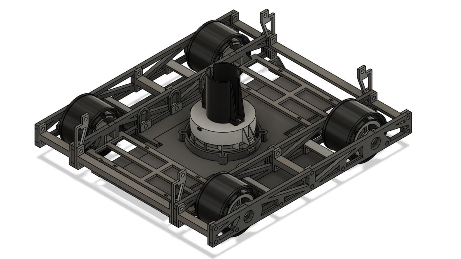
Overview
Similar to the autonomous zamboni robots that drive around to keep Kiewit and Othmer Halls clean, our project is the design and production of an autonomous window cleaning robot. We wanted our robot to be self-contained, meaning no wires or supports running to the ground, and autonomous, meaning it could be hands-free after being set on a window. To keep the walkway under the robot clear, our robot uses an impeller to produce enough suction to hold it to the glass. The impeller also generates the force necessary for the cleaning of the window. With self-saturating pads, the robot’s motion across the window causes it to clean as it drives. With four independently powered wheels, the robot is able to fully maneuver around the pane of glass. Integrated sensors allow for the robot to detect the edges of the window and turn around in order to clean the entire window.